|
introduction
thermocouples are the most widely used temperature sensor in test and development work. accurate temperature measurements can be made at low cost with shop-built probes and ordinary low-level voltmeters.
what are thermocouples and how do they work?
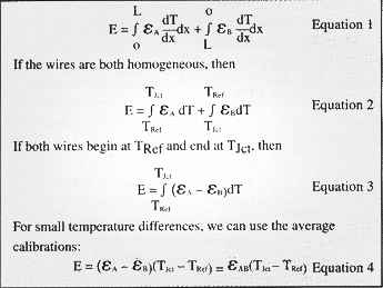
any two wires of different materials can be used as a thermocouple if connected together as in figure 1. the ab connection is called the "junction". when the junction temperature, tjct, is different from the reference temperature, tref, a low-level dc voltage, e , will be available at the +/- terminals. the value of e depends on the materials a and b, on the reference temperature, and on the junction temperature. the governing equations for two-wire thermocouples are shown in eq. 1 through to eq. 4. if a circuit has more than two wires, more terms would be needed.
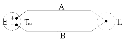
fig. 1 the simplest thermocouple.
from eq. 1, we can see that the emf is generated by the wires, not the junction: the junction being just an electrical connection between the two wires. the signal is generated in the wires where the temperature gradient, dt/dx, is not zero: uniform temperature wires do not generate any emf. if both wires are uniform in calibration, then eq. 2 can be used, and if the two wires both begin at tref and end at tjct, then eq. 3 applies.
emf-temperature tables can only be used when the circuit consists of only two wires, both of which are uniform in calibration, and both of which begin at tref and end at tjct. when only small temperature differences are involved, the values of  a and b can be treated as constants, and eq. 4 gives a good approximation to the emf. a and b can be treated as constants, and eq. 4 gives a good approximation to the emf.
thermocouple materials
the three most common thermocouple alloys for moderate temperatures are iron-constantan (type j), copper-constantan (type t), and chromel-alumel (type k).
- the first named element of the pair is the positive element.
- the negative wire is color coded red (current u.s. standards).
three grades of wire are available in each type, based on calibration accuracy: precision, standard, and lead-wire. the calibration of precision grade thermocouple wire is guaranteed within +/- 3.8% or 1°c(2°f), which ever is the larger, while standard grade is within +/- 3.4% or 2°c (4°f), and lead-wire grade within +/- 1%. the accuracy statement can be interpreted as the percent of the difference between the tjct and tref. considering the low cost of even the best material, it is hard to justify the purchase of any but precision grade material, even for extension wire.
all three types (j, k, and t) are available as insulated duplexed pairs from 0.001-inch diameter on up. for accuracy, and minimum system disturbance, the smaller the wire the better, but wire smaller than 0.003-inch diameter is very fragile.
iron-constantan: iron-constantan (type j, color coded white and red) generates about 50 µv/°c (28 µv/°f). the iron wire is magnetic. junctions can be made by welding or soldering, using commonly available solders and fluxes.
iron-constantan thermocouples can generate a galvanic emf between the two wires and should not be used in applications where they might get wet.
chromel alumel: chromel-alumel (type k, color coded yellow and red) generates about 40 µv/°c (22 µv/°f). the alumel wire is magnetic. junctions can be made by welding or soldering, but high temperature silver-solders and special fluxes must be used.
chromel-alumel thermocouples generate electrical signals, while the wires are being bent, and should not be used on vibrating systems, unless strain relief loops can be provided.
copper-constantan: copper-constantan (type t, color coded blue and red) generates about 40 µv/°c (22 µv/°f). neither wire is magnetic. junctions can be made by welding or soldering with commonly available solders and fluxes.
copper-constantan thermocouples are very susceptible to conduction error, due to the high thermal conductivity of the copper, and should not be used unless long runs of wire (100 to 200 wire diameters) can be laid along an isotherm.
thermocouple probes
the simplest (and cheapest, and quickest) thermocouple probe is simply a pair of wires twisted or crimped together at one end with the other end connected to the terminals of a voltmeter. more often, however, probes are either purchased or made in-house.
purchasing thermocouples: thermocouples can be purchased from a number of suppliers and, generally speaking, are readily available. there will be times, however, when a new thermocouple is needed - now and not tomorrow — so every lab should be able to make simple thermocouples.
shop-made thermocouples: most thermocouples needed for electronics cooling applications can be made in-house from bulk thermocouple wires bought as spools of insulated pairs. if a thermocouple welder, or any "fine-wire" welder is available, welding is generally quicker and easier than soldering. any solder which wets both wires can be used to make the junction. keep the weld bead or solder ball within 10 to 15% of the wire diameter. all other factors being the same, a thermocouple with a soldered junction is just as accurate as one with a welded junction.
reference temperature systems and zone boxes
the signal from a thermocouple depends as much on the reference junction temperature as it does on the measuring junction temperature. there are several different systems for establishing a reference temperature.
ice baths: ice baths are widely used, because they are accurate and inexpensive. any potable water freezes within about 0.01°c of zero. a drug-store thermos flask will maintain 0°c for several hours if filled with finely crushed ice, and then flooded with water.
electronically controlled references: electronically controlled reference temperature devices are available, both high temperature and ice-point. these devices require periodic calibration and generally are not as stable as ice-baths, but are more convenient.
compensated reference temperature systems: dedicated temperature indicators terminate each thermocouple at a connection panel inside the chassis and use a compensation network to inject a signal which compensates for the temperature of the panel before calculating the temperature.
zone boxes: a zone box is a region of uniform temperature used to ensure that all connections made within it are at the same temperature. the temperature need not be controlled, nor need it be measured — it need only be uniform. circuits using zone boxes are shown in figures 3 and 4.
a simple zone box can be made by gluing an electrician's barrier strip to the inside of a small, thick-walled aluminum chassis box, closed to prevent air circulation.
measuring instruments
there are two options:
- use a reference temperature bath (an ice bath, for example) and a general purpose voltmeter, interpreting the signal using a table, by hand or using software.
- use a dedicated temperature indicator with reference temperature compensation.
the reference-bath/voltmeter/table look-up system is more flexible, potentially more accurate, and can be used to measure temperature differences as well as temperature levels. dedicated temperature indicators are more convenient for routine measurements.
circuits
an ideal thermocouple consists of a pair of unbroken, homogeneous wires of dissimilar material, connected together at one end with the other end of the pair in a "reference temperature" region, as shown earlier in figure 1. as a practical matter, the signal must be brought out of the reference temperature region to a voltmeter at room temperature. this is done using a pair of copper wires (from the same spool) as shown in figure 2.
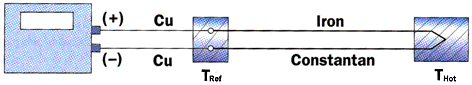
figure 2. the simplest practical thermocouple, illustrated using iron-constantan wire.
the following figures illustrate more complex circuits incorporating switches, connectors, and reference baths for single and multiple thermocouples. measurements made using these circuits will be just as accurate as those measurements obtained if each thermocouple had been "hard-wired" to its own reference bath and voltmeter.
connectors: figure 3 shows a circuit using extension wires and a connector, instead of unbroken lengths of wire. the connector can be either a thermocouple grade connector, or a barrier strip inside a zone box. if the extension wires are from the same spool of wire as the probe, this circuit is exactly equivalent to the ideal circuit.
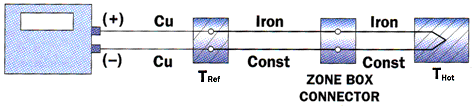
figure 3. a circuit using extension wires and a connector of a zone-box.
multiple thermocouples: figure 4 shows a circuit for reading a number of thermocouples (three shown) using a voltmeter, a uniform-temperature zone box, a double-pole selector switch (also uniform in temperature), and a reference temperature bath. multiple-conductor ribbon cable and "press-on" connectors can be used between the zone box and the selector switch. the connectors at the two ends of the ribbon cable must each be inside a zone-box but the two boxes need not be at the same temperature.
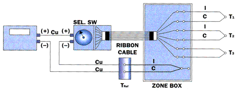
figure 4. a zone-box circuit for reading many thermocouples with mostly copper wire.
both the zone box and the selector switch box must be kept isothermal; they should both be kept away from heat sources or direct sunlight etc.
figure 5 shows another circuit for handling multiple thermocouples (three are shown), in which each voltage is read separately, including the zone-box temperature signal. the zone-box signal must be added to the signal from each channel to get the total emf, which should then be used to find the temperature.
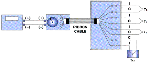
figure 5. an alternative wiring diagram for reading multiple thermocouples with one voltmeter.
the wiring should always be checked: the voltage on the reference thermocouple channel should be close to zero before the reference thermocouple is put into the ice-bath, and should correspond to the zone-box temperature afterwards.
if a dedicated multiple-channel temperature indicator is being used, the region shown here as the zone box represents the thermocouple connection panel built into the temperature indicator.
with a dedicated temperature indicator, the reference bath branch of the circuit need not be used, since the internal electronics of the system will always add a correction to the thermocouple signal based on the panel temperature.
measuring differences: the temperature difference between two points can be directly measured by connecting the two negative wires together (at room temperature) and measuring between the two positive wires. the magnitude gives the temperature difference, and the positive wire is connected to the hotter of the two locations. this approach offers no advantage in accuracy over reading the two thermocouples separately and subtracting the temperatures. figure 6 shows a 4-wire circuit which yields very high precision in the measurement of small temperature differences. one pair is used as a thermocouple to determine the temperature level, and one pair is used to determine the temperature difference between two points.

figure 6. using a four-wire thermocouple to check for electrical noice picked up in the circuit.
the two copper extension wires should produce no emf, regardless of the temperature level. this can be confirmed by running the system initially with a shorting link across the two copper wires, inside the local zone box. the "local calibration" (microvolts/degree at the measured temperature level) should be used to interpret the difference voltage. using precision grade wire, the measurement is accurate to within +/- 3/8% of the difference, providing the temperature in the local zone box is close to one of the two measured points.
checking for electrical pick-up: a 4-wire thermocouple can be used both to measure temperature and to check for electrical pick-up. all four wires are soldered together to form the measuring junction. reading either pair as a thermocouple yields the temperature of the junction. reading across either pair of similar wires checks for electrical pick-up: two similar wires can not generate a thermoelectric signal so, if there is a voltage across the two iron wires that is clear evidence of electrical noise.
measuring surface temperature
there are three main problems in surface temperature measurement: (1) deciding what needs to be known about the surface temperature, (2) choosing a representative location to measure it, and (3) getting the thermocouple in good thermal contact at the chosen location.
the two most frequently asked questions are:
(1) what is the maximum temperature?
(2) what is the average surface temperature?
surface temperatures can vary widely on plastic encapsulated components. the hot-spot may be small, only 1/4-inch in diameter, and sharply peaked, and the measured temperature will depend sharply on the thermocouple location. the best practice would be to use a visualizing technique first (liquid crystal, or infra-red) and then put the thermocouple on the hot spot.
to ensure an accurate surface temperature measurement, a length equal to about the diameter of approximately 20 wires (including the insulation) must be glued down along an isotherm using thermally conductive cement. for a point measurement, wrap that length into a tight, flat spiral coil. alternatively, solder the junction to a piece of copper bus-bar tape (3m company), perhaps 1/16 inch square, and glue that to the surface.
always use the smallest wire that can be handled without too much breakage.
measuring gas temperature
there are three main problems in air temperature measurement:
(1) deciding what you want to know about the air temperature,
(2) choosing a representative location to measure it, and (3) breaking the thermal connection between the thermocouple junction and the hardware that supports it.
cooling air temperature varies widely across a flow passage especially near heated surfaces. the most common questions are:
(1) what is the average temperature? and, (2) what is the effective temperature of the coolant at this location?
the average temperature (the bulk mean temperature) is a fictitious temperature, defined in terms of the total thermal energy carried by the flow. there is no good location for measuring it. the only practical approach is to estimate the flow rate and heat release and calculate the average temperature.
the effective temperature of the coolant is the temperature that an isolated, passive component would achieve: the adiabatic temperature of the component, in a thermodynamic sense. for a passage heated mainly from one side, the effective temperature of the coolant at the heated wall is always higher than the average, due to temperature stratification in the coolant.
a thermocouple slightly upstream of a component, and slightly above its top surface will probably read close to the effective temperature, for that component. the effective temperature is different for each component since it depends on the streamlines striking it.
when measuring air temperature, isolate the thermocouple junction from the hardware that supports it. generally speaking, about 20 diameters must be exposed to the flow between the junction and the point of attachment. install the junction "looking upstream" with the wires trailing downstream along the flow.
the smallest wire that can be handled without breakage should be used.
dr. robert j. moffat
professor of mechanical engineering (emeritus)
stanford university
stanford, ca
|


