|
introduction
the cooling efficiency concept has been used for more than 10 years and its effectiveness has been proven in hundreds projects. it is however still only practiced by a small minority of thermal designers but in this group it is regarded as key concept. the reasons for this will hopefully become apparent in this and the following expose on the subject.
there are three major employment areas for the concept: as a meter on how well the pcb surface is used for cooling, for thermal estimates and for thermal specifications. each of these matters represents both important and frequent activities in thermal design. the fact that the cooling efficiency concept can facilitate them considerably should therefore be an important incitement for thermal designers around the world to learn more about the subject.
the first part of this presentation deals with the definition and the importance of temperature criterions. the next part will deal with various forms of applications.
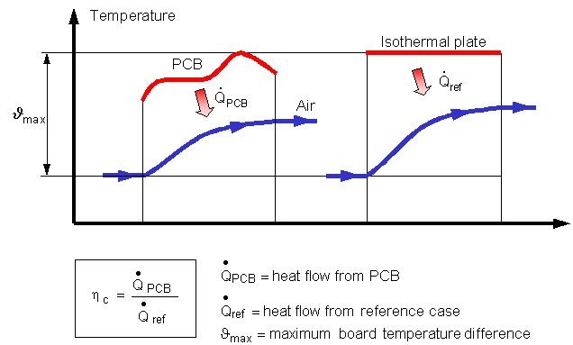
fig. 1 - definition of the cooling efficiency
definition
the cooling efficiency is defined as the ratio of the heat that can be dissipated from a pcb and a reference case. the reference case is defined as an ideal smooth isothermal parallel plate case with a temperature level that equals the maximum temperature of the pcb plate, figure 1.
quite apparent other requirements for the reference case is that the plates must have the same size, thickness, surface-to-surface distance and air flow as the pcb. what might be less apparent, is that it must not include radiation.
basic equations
the origins of various heat transfer equations are in most cases quite irrelevant to the application engineer. it is sufficient to know that they work and when they can be applied. to fully understand the cooling efficiency concept it is however important to go to the bottom of things.
the generally accepted way to characterise convection is to use a heat transfer coefficient. what may have escaped some minds is that the basic formulation for all types of convection, often called newton's cooling equation, actually mirrors a definition.
figure 2 shows the fundamental equations involved in the cooling efficiency definition and how it is possible to create an equation that exactly predicts the heat dissipated from a pcb.

figure 2
the cooling efficiency definition makes it possible to create an equation that exactly
predicts the heat dissipated from a pcb.
equation 1 is the general definition for the heat transfer coefficient. the parameters involved are not exactly defined. this equation should therefore be regarded more as principle declaration than an expression that actually can be applied. equation 2 is newton's cooling equation, which simply mirrors equation 1.
equation 3 is also a definition of the heat transfer coefficient but in this case with the difference that its parameters are clearly defined. equation 4 follows from equation 3.
equation 5 is the definition of the cooling efficiency and it should be kept in mind that it only is valid if the conditions discussed above are fulfilled.
equation 6 is a combination of equations 4 and 5. it is important to note that this equation is a logical consequence of two definitions. since a definition by definition always is true, it follows that equation 6 must be true. it can therefore not be criticised for what it is but it can of course always be criticised for being purposeless or impractical. part 2 of this expose will therefore essentially be a list of arguments why this not is the case.
the fact that equation 6 is exact is important. all errors that appear when it is applied must therefore originate from errors within its parameters and not from the equation itself. this is a great strength and one apparent consequence is that it can be used for exact specifications.
the temperature difference used for the equations in figure 2 is the inlet temperature difference. this is somewhat unusual. most heat transfer literature uses the arithmetic or the logarithmic definitions for the parallel plates flow case. heat transfer coefficient values based on the inlet temperature difference are therefore somewhat difficult to find. the smoothest work around for this problem is to convert available heat transfer coefficients to the inlet temperature difference definition.
a related issue that often pops up is if calculations that involve the cooling efficiency always must be based on the inlet temperature difference. the answer to this question is that the cooling efficiency can be regarded as a correction factor for the heat dissipated from the reference case. how the reference case is calculated has no importance. it is therefore not necessary to use the inlet temperature difference to calculate the reference case but it facilitates things.
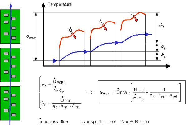
figure 3 - the cooling efficiency applied to a serial cooling case.
serial cooling
serial cooling is a term that often is used for cases where the same airflow consecutively cools several pcbs, figure 3. the maximum temperature difference for the top pcb is in these cases composed of two parts. one that accounts for the air temperature increase from the pcbs below and one that accounts for convection from the top pcb.
figure 3 shows an equation for a simplified case in which it is assumed that all pcbs have the same heat dissipation and pitch. the equation for the general case is slightly more complex.
it should be noted that the maximum board temperature difference in the serial cooling case no longer is proportional to the cooling efficiency. it can therefore be argued that the cooling efficiency concept is more important for single than for serially cooled pcbs.
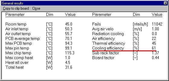
figure 4 - the most practical approach to find a cooling efficiency value is to let a
thermal pcb program extract it from the calculation result.
cooling efficiency values
the value of the cooling efficiency is given by its definition. there are basically two ways to find it, by measurement or by calculation. the problem with the former method is that the hardware must exist. the problem with the latter method is that there always will be calculation errors. since the cooling efficiency primarily is used in the design phase, there is not much choice.
almost all cooling efficiency values are therefore calculated. the smoothest approach is to let a thermal pcb program extract them from the calculation result, figure 4. the fact that the reference case is an ideal parallel plates flow case, makes this extraction quite simple.
the quality of the cooling efficiency values obtained in this way is the same as the quality of the calculated temperatures. a benchmark of the program used is therefore also a benchmark of its ability to calculate the cooling efficiency values correctly.
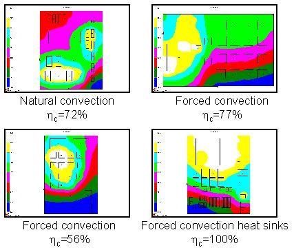
figure 5 - examples of cooling efficiency values.
figure 5 shows some examples of calculated values for multi-layer pcbs. it is striking that the values are relatively high, which is a strong argument for the pcb oriented thermal design approach.
everything that makes a pcb deviate from the isothermal reference case will have an impact on the cooling efficiency, positively or negatively. there are many factors that can have an impact in this respect. the two most obvious ones are the thermal conductivity of the pcb plate and the distribution of the heat sources.
it could be tempting to assume that 100% is the maximum limit for the cooling efficiency. this is however not quite the case. heat sinks can push the value above the 100% limit. even a plain pcb can, at least in theory, also surpass this limit.
the reason for this is that the cooling efficiency is based on the maximum board temperature. the surface temperatures of the components are however frequently higher. the components on a high density pcb can therefore boost the heat dissipation to such an extent that they more than counterbalance the low board temperatures found between the components.
the highest cooling efficiency value that the author has seen for a pcb without heat sinks, is 102%. a student in a training class created it and the lay out was in this case totally free from any other considerations than the thermal ones. the highest corresponding value for an actual design is 90%. it was made by a pcb designer who took a great pleasure in challenging the author's rule of thumb that cooling efficiencies above 80% are almost impossible to achieve without some kind of surface extension.
heat radiation exchange with the sideboards can also alter the cooling efficiency significantly. this impact is most accentuated in natural convection. in extreme cases it can change the cooling efficiency as much as 30%.
a phenomenon that will change the order of the values disused above, are the air disturbances that are created in the inlets to modern emc-shielded sub racks? these shields can create massive vortex formations that increase the heat transfer coefficient as much as 60%, even if 30% is more typical. there is not yet sufficient data available to discern more precise numbers. this phenomenon must nevertheless result in a general increase of the cooling efficiency.
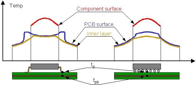
figure 6 - temperature conditions below components.
board temperature
the board temperature concept appears with an increasing frequency in the electronics cooling literature. it is a well-found name for the temperatures on pcbs in general but it is too vague for calculation purposes.
figure 6 shows two examples of temperature profiles below components. the inner ground and voltage layers, which contrary to the signal layers are almost intact, carry the main part of the heat that is spread out on a pcb. the heat that is pushed down into a pcb must therefore first overcome the thermal resistance caused by the thin layer of basic pcb material that separates the surface pads from the inner layers.
this resistance it not negligible. it is in fact sometimes of the same order as the inner thermal resistances in the component. the temperature on the pads can therefore be significantly higher than the temperature of the inner layer. some cases are even so critical that the component manufacturer recommends the user to create a certain number of extra thermal connections between the pads and the inner layers, so called thermal vias.
the temperature outside the pads declines very fast towards the inner layer temperature. the properties of pcb material and the critical length of the signal lines emerging from the pads, determine this gradient. the critical length of a signal line is the length at which its temperature is almost the same as the inner layer temperature. for typical pcbs it is of the order a few millimetres. the surface temperature gradients in the vicinity of a component are therefore normally quite steep.
as indicated in figure 6 it is reasonable to operate with two board temperatures below components. one that is representative for the pads, tp, and one that is representative for the inner layer temperature below the pads, tpb. it is also good practice to let the way a thermal component model is connected to the pcb reflect this, figure 7.
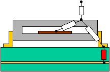
figure 7 - the difference between the pcb surface and
the inner layer temperature below a component
should be reflected in the way its thermal component model
is connected to the pcb.
the board temperature as thermal criterion
the cooling efficiency can be used for several different purposes. one obvious purpose is as a meter for how well the pcb surface is used as a heat sink. this employment is relatively uncomplicated and does not require any thermal criterion. other purposes, for example to estimate the maximum heat dissipation that can be allowed on a pcb, can not be made without a board temperature limit.
the cooling efficiency is defined for the temperature difference given by the maximum inner layer temperature, tpb, with the nomenclature used above, and the inlet temperature of the air. there are at least two problems associated with this definition. the first and most important one, is whether it is reasonable to base a thermal design on a board temperature criterion. the second one, is the measurement problem.
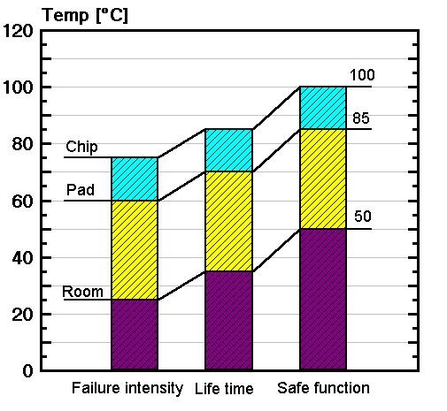
figure 8 - an example on how temperature limits can be specified.
figure 8 shows an example of a how temperature limits can be specified. although this particular example in many aspects has been overridden by the rapid development of modern hardware, it still reflects the fundamentals. what is somewhat unusual with these limits, is that they not only specify a chip temperature limit but also pad temperature limit.
there are several arguments for why the maximum pad temperature should be limited. they are about items such as solder point fatigue and pcb discoloration. it is far beyond the author's expertise to evaluate these. an argument the author understand however, is that the passive components that often surrounds active components not can be allowed to overheat.
what is of outmost importance is the level of the pad temperature limit. if the pad temperature limit for the safe function case in figure 8 was set to 75 oc instead of 85 oc, the available temperature difference would decrease from 35 oc to 25 oc and the corresponding maximum allowed heat dissipation would decrease with 30%!
an annoying matter is also that the cooling efficiency is defined for the maximum inner layer temperature and not for the maximum pad temperature. this difference is usually not a major concern but it can some times complicate things. a third problem is that the pad temperature not can be measured for modern array type of components.
as so many times before, the conclusion of this discussion is that the quality of a calculation procedure never can exceed the quality of the temperature limits.
conclusions
the definition of the cooling efficiency concept makes it possible to create an exact equation for the heat that can be dissipated from a pcb.
cooling efficiency values can be extracted from the results calculated by a thermal pcb program. the accuracy of these results equals the accuracy of the program.
the cooling efficiency values for multi-layer pcbs are often quite high and values above 100% can be achieved if heat sinks are used.
modern emc-shielded sub racks create turbulence phenomenon that considerably can enhance the cooling efficiency. there are not yet sufficient experience values available to be more specific about this impact.
calculations based on the cooling efficiency concept must use a board temperature criterion. it is somewhat problematic to determine the quality of that criterion.
it is well motivated to define two types of board temperature below a component. one that is representative for the surface pads and one that is representative for the temperature of the inner layer below the pads.
about ake malhammer

ake obtained his master of science degree in 1970 at kth, (royal school of technology), stockholm. he then continued his studies and financed them with various heat transfer-engineering activities such as deep freezing of hamburgers, nuclear power plant cooling and teaching. his ph.d. degree was awarded in 1986 with a thesis about frost growth on finned surfaces. since that year and until december 2000 he was employed at ericsson as a heat transfer expert. currently he is establishing himself as an independent consultant.
having one foot in the university world and the other in the industry, ake has dedicated himself to applying heat transfer theory to the requirements of the electronic industry. he has developed and considerably contributed to several front-end design methods, he holds several patents and he is regularly lecturing thermal design for electronics.
to read ake's web site for more thermal information and software tools he has developed, please visit http://akemalhammar.fr/ - see more at: https://www.coolingzone.com/library.php?read=534#sthash.y3rcxrow.dpuf
to read ake's website for more thermal information and software tools he has developed, visit http://akemalhammar.fr/.
|