|
the increasing power density of electronic devices has pushed traditional air cooling technology to its performance limit. with air as a working fluid, it is increasingly difficult to design cost-effective heat sinks that can dissipate over 100 w/cm2 heat flux at the device level. liquid cooled heat sinks have emerged as the accepted substitute for air cooled heat sinks because of their better performance and smaller size.
in liquid cooling technologies, the microchannel heat sink is the most promising one to be used for device level cooling. in 1981, tuckerman and pease [1] experimentally showed that single-layer microchannels etched directly into the back of silicon wafers are very effective for dissipating heat. using water as the working fluid, they demonstrated that these microchannels can eliminate a maximum of 790 w/cm2 of heat.
the magic behind microchannel heat sinks is their ability to achieve a high heat transfer coefficient and to create a large surface area. the heat dissipation ability of liquid cooled heat sinks is determined by the heat conduction in solid material and heat convection in the fluid. normally convection is the dominant factor for reducing thermal resistance when highly conductive material is used to fabricate the heat sinks. for a fully developed laminar flow in a square channel with constant wall temperature or constant wall heat flux, the nusselt number is a constant. the heat transfer coefficient can be calculated by the following equation,

where is the thermal conductivity of fluid, and is the hydraulic diameter of the channel. equation 1 shows that the heat transfer coefficient is inversely proportional to the channel hydraulic diameter. by reducing the channel size, a larger heat transfer coefficient can be obtained.
the thermal resistance of single channels scales with the product of, where is the surface area. the of a single channel does not depend on because the surface area scales as. for a confined geometry, there are more channels for small hydraulic diameters than large ones. so the heat sink with a smaller hydraulic diameter provides better overall thermal performance.
on the other hand, the friction factor for a fully developed laminar flow in a square channel is also a constant. the pressure drop across the channel is determined by the equation,
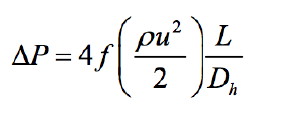
where is friction factor, is flow velocity, and is channel length.
the pressure drop is also inversely proportional to the channel hydraulic diameter. so for constant flow velocity, the smaller the channel means the larger the pressure drop.
as illustrated by equations 1 and 2, there is a dilemma between improving a microchannel heat sink’s thermal performance and its hydraulic performance. to reduce the thermal resistance, the size of the channel should decrease. but, when channel size reduces, the pressure drop across the channel will increase. that means more pumping power is needed to drive the flow.
there are many ways to enhance the microchannel performance. some of these aim to increase the convective heat transfer coefficient, some focus at reducing pressure drop, and some work on both objectives. the general methods used for performance enhancement can be summarized as follows:
- a high aspect ratio channel
- fin enhancement
- flow optimization
- multilayer microchannel structure
- two-phase flow inside the microchannel
the above methods will be generally explained one by one. how to implement these methods is the engineer’s choice. the following paragraphs discuss the advantages and limitations of these methods.
1. the benefits of a high aspect ratio channel
using a deeper channel will increase the convective heat transfer and reduce the pressure drop of microchannel heat sinks. compare the two different channel geometries in figure 1.
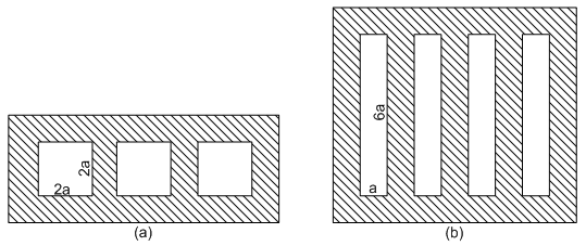
figure 1. microchannel arrangement (a) square channel, (b) rectangular channel.
for the square channel arrangement, the hydraulic diameter is 2a, the wetted boundary is 24a, and the total channel cross section area is 12a2. for the rectangular channel arrangement with an aspect ratio of 6, the channel hydraulic diameter is

the total wetted area is 56a and the total cross section area is 24a2. the rectangular channel has a smaller hydraulic diameter and much larger wetted surface and cross section areas. this means it can achieve much smaller thermal resistance and pressure drop. it works like an air-cooled heat sink with long fins. but there is a limit on fin height for the microchannel structure. the limit is confined by manufacturing technology and conduction inside solid material. on one hand, it is difficult to create large aspect ratio channels with uniform wall thickness in the micro scale. on the other hand, the microchannel fin efficiency decreases quickly with the increase of channel height, because of its high convective heat transfer coefficient. that means that the overall thermal resistance will not change beyond a certain channel height and the conductive resistance inside the solid becomes significant. so there exists an optimized channel aspect ratio, and the thermal engineer must find the best solution between performance and cost.
2. fin enhancement
there are many ways to enhance fin performance. figure 2(a) is the regular straight fin layout. figure 2(b) shows the layout with break down fins, which will improve the flow mixing and reduce the pressure drop. figure 2(c) shows the layout with staggered fins. this layout can break the boundary layer and achieve a larger heat transfer coefficient on individual fins. figure 2(d) shows the complex diamond fin layout.
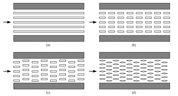
figure 2. fin arrangements (a) straight fins, (b) broken fins, (c) staggered fins, (d) staggered diamond fins.
3. flow optimization
changing microchannel heat sink structure to create better flow is another way to get better heat sink performance. figure 3 illustrates one example of flow optimization. in this microchannel heat sink, there are two inlets and two outlets. the flow is split in the middle. the thermal performance of this structure is similar as that of a straight fin layout as figure 2(a). because the flow length is reduced by half, the pressure drop is also reduced by half when it is compared with figure 2(a).
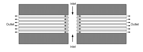
figure 3. microchannel with multiple inlets, outlets and split flow.
4. the benefits of a multilayer microchannel structure
using a multilayer microchannel structure can achieve both good thermal and hydraulic performance. figure 4 shows two examples of multilayer microchannel heat sinks.
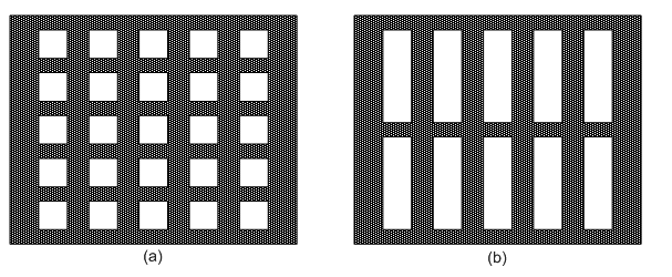
figure 4. multilayer microchannel heat sinks (a) square channel, (b) rectangular channel.
the multilayer structure keeps the channel hydraulic diameter small which results in a high heat transfer coefficient and increases the wetted areas between solid and liquid. this helps reduce the total thermal resistance. it also keeps the channel cross section area large, which leads to a smaller pressure drop. the multilayer structure can also overcome the channel height limit from manufacturing technology and can make the heat sink thicker. obviously this will mean increased cost and technical difficulties when creating a multilayer microchannel structure.
5. two-phase flow inside a microchannel
boiling inside microchannels can generate a heat transfer coefficient which is multiple times larger than can be achieved by single-phase flow. introducing two-phase flow into microchannels is a natural solution for extreme high heat flux applications, such as laser diodes, power transistors and radar arrays. the two-phase flow also brings technical challenges, such as high pressure drop, flow stability and durability. for more information, readers can refer to these previous qpedia articles: heat transfer coefficient correlations for two-phase flow in small channels [2] and critical heat flux of boiling in microchannels [3].
the microchannel enhancement methods discussed above are not isolated. they can be combined together depending on a project’s thermal requirements, size limitation and budget. as more understanding of heat transfer in microchannel and advancement of manufacturing technology is obtained, microchannel heat sinks will find more applications in electronic cooling.
references:
1. tuckerman, d. and pease, r., high-performance heat sinking for vlsi, ieee electron dev. lett., may 1981.
2. heat transfer coefficient correlations for two-phase flow in small channels, qpedia thermal e-magazine, may 2009.
3. critical heat flux of boiling in microchannels, qpedia thermal e-magazine, march, 2010.
|