|
general methods for measuring thermal conductivity
this article provides an overview of the principal methods for measuring thermal conductivity, particularly in electronics thermal management. designing successful electronics cooling solutions requires an accurate knowledge of the thermal and mechanical properties of the various materials involved. these materials include silicon, copper, aluminum, fiberglass, epoxies, plastic resins and ceramics. printed circuit boards and their attached components are all made from these substances, whose individual and combined thermal conductivities are critical to thermal performance of the system from the component level through to full scale assemblies and enclosures.
introduction
two quantities govern heat transfer in an object: thermal conductivity and thermal diffusivity. thermal conductivity is considered the more important quantity for thermal management because of the length scales encountered with electrical devices and printed circuit boards. the dynamic effects of thermal diffusivity are important for analyzing extremely local and rapidly changing heat loads. electronic assemblies do not typically function in this manner.
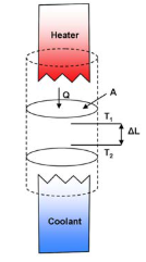
thermal conductivity, k in general, is measured as shown in figure 1. it is defined as:

where:
q = the amount of heat passing through a cross section (w)
a = the cross-sectional area (m2)
?t = the temperature difference (°c)
?l = the material thickness (m)
q / a = the heat flux causing the thermal gradient, ?t / ?l.

figure 1. typical thermal conductivity measurement diagram [1].
choosing a measurement method
many techniques exist for measuring the various thermal quantities [2]. each one has its own requirement for sample size and shape, degree of accuracy, cost, complexity, etc.
the four principal measurement techniques [2]
- long bar with steady heating – the most traditional method for measuring thermal conductivity uses a bar with one dimension significantly longer than the other two. a controlled amount of heat is introduced at one end of the bar while the opposite end is thermally grounded.
- long bar with periodic heating – rather than steadily heating a long bar, it can be beneficial to generate thermal waves by applying time-dependent heat to a sample. the analysis of thermal waves generated by periodic heating is a technique pioneered by angstrom in the 19th century.
- three-omega method – the thermal conductivity of a sample near its surface can be measured by the periodic use of a suitable metallic heater in direct contact with the sample. typically a thin metallic line heater equipped with separate current and voltage leads is connected to an ac electrical power source. this generates an oscillating temperature; the measured voltage then has a component v3ω at a frequency of 3ω. for this reason, the method is sometimes called the 3ω method.
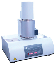
- flash method – this is particularly useful for measuring the thermal diffusivity of a thin, free- standing, homogeneous plate. it consists of heating one side of a sample plate with a pulse of radiation from a flash lamp or laser. simultaneously, the temperature of the opposite side is monitored for the arrival of the heat wave. figure 2 shows the apparatus used for the flash method of measuring thermal diffusivity.

figure 2. the linseis lfa 1000 laser flash instrument for determining thermal diffusivity,
conductivity and specific heat values [3].
comparing all techniques
tables 1 through 3 summarize the various methods for measuring thermal conductivity. table 1 shows these methods grouped according to the time dependence of the heat applied to the sample – steady-state, periodic and pulsed. the methods differ principally by the geometry of the sample and heater, and also by the use of thermometry. the remarks in table 1 include the particular advantages, disadvantages or peculiarities of each method. table 2 shows the quantities being measured, percentage of uncertainty, and relative cost. table 3 shows the equipment needed for measuring thermal conductivity or thermal diffusivity. the numbering sequence is the same in each table.
table 1. descriptions of different methods for measuring thermal conductivity.
|
|
#
|
method
|
description
|
|
steady heating
|
1
|
end-heated bar
|
classic technique for measuring k over a wide temperature range. two heaters or many thermocouples can be used to detect and correct for any surface heat losses that may be present. requires samples with parallel edges. high accuracy (1%) is possible with operator care.
|
|
2
|
insulated bar or plate
|
minimizes heat loss from the sample surface. thermometers can be permanently mounted for quick measurement.
|
|
3
|
solid cylinder, axial heater
|
minimizes surface heat loss. good for low-conductivity materials to high temperatures. sample preparation generally tedious.
|
|
4
|
radiating bar
|
good for a thin bar of material. uses radiation to an advantage, but requires knowledge of the emissivity.
|
|
5
|
line-heated thin plate
|
for thin free-standing films. uses lithography to deposit evaporated heaters and thermometers on a length scale small enough to minimize the effects of radiation.
|
|
6
|
bridge method
|
measures interface resistance between a film of material and a substrate. uses small heaters and thermometers deposited by thin-film techniques.
|
|
7
|
transient dc
|
measures conductivity and diffusivity. requires two samples to avoid radiation losses. good for low to medium conductivity.
|
|
periodic heating
|
8
|
heated bar
|
classic technique pioneered by angstrom. avoids surface heat loss problems by a high enough heating frequency, or by measuring phase and/or amplitude, possibly at several frequencies.
|
|
9
|
spot-heated plate
|
generates radial waves which can be detected by, for example, infrared imaging or the mirage effect. the operating frequency is usually chosen so that the thermal length is much greater than the sample thickness, but less than the sample length or width. sample outline not important.
|
|
10
|
spot-heated solid
|
generates hemispheric waves, detectable by infrared or mirage scanning of the surface. needs only one flat surface. sample outline not important. measurement depth is determined by the operating frequency.
|
|
11
|
line-heated plate (3 ω)
|
requires narrow, metallic heater/thermometer on sample surface. determines k. can be used at high temperature by operating at sufficiently high frequency to avoid surface heat loss problems. useful in liquids with thin-wire heater.
|
|
12
|
plane-heated plate (3 ω)
|
requires large-area metallic heater on surface. determines kρc. useful in liquids.
|
|
pulse heating
|
13
|
converging wave
|
good for plate-shaped sample of arbitrary outline. the ring radius is usually chosen to be much larger than the sample thickness.
|
|
14
|
thermal grating (surface)
|
measures α near the surface of a material to a depth selected by the period of the grating. capable of fine spatial resolution on surface (~20 mm).
|
|
15
|
thermal grating (bulk)
|
sample must be semitransparent at the laser wavelength. little sample preparation.
|
|
16
|
uniform surface heating (flash)
|
good for a thin plate of material. transparent samples need an absorbing layer at least one face. wide range of diffusivities measurable.
|
|
17
|
photo-thermal reflectance
|
good for examining very local (~5μm) variations in the thermal properties on a surface. has been applied to films
|
table 2. summary of techniques for measuring the thermal properties of materials
|
technique
|
quantity measured
|
typical uncertainty
|
temperature range
|
sample geometry
|
sample preparation
|
operator skill
|
relative cost
|
|
dc
|
|
|
|
|
|
|
|
|
1. heated bar
|
kii
|
5-10%
|
0-600 k
|
uniform bar
|
detailed
|
moderate
|
low
|
|
2. insulated bar or plate
|
kii
|
10%
|
300-400 k
|
plate or bar
|
none
|
moderate
|
low
|
|
3. solid cylinder
|
kr
|
10%
|
0-2000 k
|
cylinder
|
axial heater
|
moderate
|
low
|
|
4. radiating bar
|
kii
|
10%
|
400-600 k
|
uniform bar
|
black coating
|
moderate
|
low-medium
|
|
5. line-heated plate
|
kii
|
5%
|
0-500 k
|
plate
|
detailed
|
moderate
|
low
|
|
6. bridge
|
ki, rt
|
10-20%
|
0-600 k
|
film on substrate
|
detailed
|
moderate
|
low
|
|
7. transient dc
|
ki, αi
|
10%
|
0-600 k
|
thick plate
|
moderate
|
moderate
|
low
|
|
periodic
|
|
|
|
|
|
|
|
|
8. heated bar
|
kii, αii
|
10%
|
0-600 k
|
uniform bar
|
varied
|
moderate
|
low
|
|
9. spot-heated plate
|
αii
|
10%
|
200-1000 k
|
plate
|
black coating
|
moderate
|
medium
|
|
10. spot-heated solid
|
αavg
|
10%
|
100-400 k
|
flat surface
|
black coating
|
high
|
high
|
|
11. line-heated plate (3ω)
|
kavg
|
5-10%
|
0-1000 k
|
flat surface
|
narrow heater
|
moderate
|
medium
|
|
12. plane-heated (3ω) pulsed
|
k? ρ?
|
5-10%
|
0-1000 k
|
flat surface
|
broad heater
|
moderate
|
medium
|
|
pulsed
|
|
|
|
|
|
|
|
|
13. converging wave
|
αii
|
10%
|
300-1000 k
|
plate
|
black coating
|
moderate
|
medium
|
|
14. thermal grating (surface)
|
αii
|
10-20%
|
100-1000 k
|
flat surface
|
black coating
|
high
|
medium
|
|
15. thermal grating (bulk)
|
α^
|
10-20%
|
100-1000 k
|
flat surface
|
none
|
high
|
high
|
|
16. flash method
|
α? (αii)
|
10%
|
200-1000 k
|
plate
|
black coatings
|
moderate
|
medium
|
|
17. photo-thermal reflectance
|
α1,rt
|
20%
|
200-1000 k
|
flat surface
|
metal coating
|
high
|
high
|
note: kr refers to the radial component of conductivity for heat flow perpendicular to the cylinder axis, and rt indicates interface resistance.
table 3. equipment needed for measuring thermal conductivity and/or diffusivity [2].
|
technique
|
tc
voltmeter
scanner
|
power supply
|
vacuum sample prep.
|
vacuum measurement
|
pulsed laser/fl
|
cw laser
|
special lenses, etc.
|
detectors, cameras
|
lock-in amplifier
|
signal averager
|
|
dc
|
|
|
|
|
|
|
|
|
|
|
|
1. heated bar
|
y
|
dc
|
opt.
|
y
|
|
|
|
opt.
|
|
|
|
2. insulated bar or plate
|
y
|
dc
|
opt.
|
y
|
|
|
|
opt.
|
|
|
|
3. solid cylinder
|
y
|
dc
|
|
opt.
|
|
|
|
|
|
|
|
4. radiating bar
|
|
dc
|
|
y
|
|
|
y
|
y
|
|
|
|
5. line-heated plate
|
y
|
dc
|
y
|
opt.
|
|
|
|
|
|
|
|
6. bridge
|
y
|
dc
|
y
|
|
|
|
|
|
|
|
|
7. transient
|
y
|
dc
|
|
|
|
|
|
|
|
opt.
|
|
periodic
|
|
|
|
|
|
|
|
|
|
|
|
8. heated bar
|
|
ac
|
opt.
|
|
|
|
|
opt.
|
y
|
|
|
9. spot-heated plate
|
|
|
opt.
|
|
|
mod.
|
|
y
|
y
|
|
|
10. spot-heated solid
|
|
|
opt.
|
|
|
mod.
|
|
y
|
y
|
|
|
11. line-heated plate (3ω)
|
|
ac
|
y
|
|
|
|
|
|
y
|
|
|
12. plane-heated (3ω) pulsed
|
|
ac
|
y
|
|
|
|
|
|
y
|
|
|
pulsed
|
|
|
|
|
|
|
|
|
|
|
|
13. converging wave
|
|
|
opt.
|
|
y
|
|
y
|
y
|
|
y
|
|
14. thermal grating (surface)
|
|
|
opt.
|
|
laser
|
y
|
y
|
opt.
|
|
y
|
|
15. thermal grating (bulk)
|
|
|
opt.
|
|
laser
|
|
y
|
y
|
|
y
|
|
16. flash method
|
|
|
opt.
|
|
y
|
|
y
|
y
|
|
y
|
|
17. photo-thermal reflectance
|
|
|
opt.
|
|
y
|
y
|
y
|
y
|
|
y
|
note: details of the equipment are given in the text. tc, thermocouple; fl, flash amp; y, yes; opt., optional; mod, modulated.
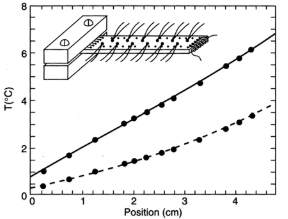
figure 3 shows data obtained by measuring the in-plane thermal conductivity of a sample of printed wiring board with many vias. twelve thermocouples attached along the center line of the sample are used to measure the gradient generated by a heater at the free end. copper wire looped through holes at either end is used to improve thermal contact of the sample with both the heater wire and thermal ground. the lower set of data is obtained with an atmosphere of air around the sample; the upper set is obtained with a vacuum and radiation shields placed around the sample [5].

figure 3. data obtained by measuring the in-plane thermal conductivity, k of a sample of
printed wiring board with many vias [2].
in the figure 3 set up, thermal conductivity is measured from
k = q/a(?t/ ?x)
where:
a = cross-sectional area = 0.1 cm2
and
(?t/ ?x) = temperature gradient measured by the thermocouples
commercial vendors
instruments for measuring thermal conductivity, thermal diffusivity or specific heat are available from many equipment manufacturers and suppliers, including:
- anter corp., 1700 universal rd. pittsburg, pa 15325 [2]
- holometrix inc., 25 wiggins ave., bedford, ma 01730 [2]
- netzsch instruments, wittelsbacherstrasse 42, p.o. box 1460, d-95088 selb, germany [2]
- orton instruments, 6991 old 3c highway, westerville, oh 43081 [2]
- sinku-riko inc., c/o ulvac technologies, inc., 300 hakusan-cho, midori-ku yokohama 226, japan [2]
- theta industries inc., 26 valley rd. port washington, ny 11050 [1]
standard measurement techniques [4]
the following are referenced standards that are used for measuring thermal properties of solids and liquids.
- ieee standard 442-1981, "ieee guide for soil thermal resistivity measurements"
- ieee standard 98-2002, "standard for the preparation of test procedures for the thermal evaluation of solid electrical insulating materials"
- astm standard d5470-06, "standard test method for thermal transmission properties of thermally conductive electrical insulation materials"
- astm standard e1225-04, "standard test method for thermal conductivity of solids by means of the guarded-comparative-longitudinal heat flow technique"
- astm standard d5930-01, "standard test method for thermal conductivity of plastics by means of a transient line-source technique"
- astm standard d2717-95, "standard test method for thermal conductivity of liquids"
- iso 22007-2:2008 "plastics -- determination of thermal conductivity and thermal diffusivity -- part 2: transient plane heat source (hot disc) method"
summary
the set up and solution of the measurement methodology difficulty impacts and complicates the measurement process. the wide choice of methods may first appear to be a disadvantage. however, once understood for their application-specific benefits – the advantages become evident. materials to be tested, part geometry and part test temperatures will usually be the primary criteria. as always, the relative cost and expected level of accuracy will also be important factors. avoiding complicated boundary conditions, irregular part geometry, difficult heater placement/construction and encouraging the difficult task of one-dimensional heat flow will greatly simplify the measurement process. multiple benefits will result from reducing the cost and assembly difficulty of the experimental set-up while avoiding those errors often introduced when attempting to construct complicated analytical/mathematical models.
references:
1. principal methods of thermal conductivity measurements, http://www.anter.com/tn67.htm
2. azar, k., thermal measurements in electronic cooling, crc press, 1997.
3. laser flash thermal conductivity measurement, http://www.linseis.net/html_en/thermal/laserflash/lfa_1000.php
4. thermal conductivity (wikipedia) http://en.wikipedia.org/wiki/thermal_conductivity azar, k. and graebner, j., experimental determination of thermal conductivity of printed wiring.
5. boards, proc. of ieee semi-therm, 1996.
|