|
a heat pipe is a device with high thermal conductance that can transport large amounts of heat with small temperature differences between its hot and cold ends. it is normally used to transport heat from one location to another location or to smooth the temperature distribution on a solid surface. the heat pipe is widely used in aerospace applications, military devices, temperature control system, and personal computers.
the heat pipe is a self-driven, two-phase heat transfer device. a schematic view of the heat pipe is shown in figure 1. at the hot section (evaporator), the liquid evaporates and turns to vapor. the vapor flows to the cold section (condenser) and liquifies there. the liquid is driven back from the cold section to the hot section by a capillary force induced by the wick structure.
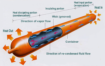
figure 1. typical heat pipe [1]
the heat transfer ability of the heat pipe is determined by its diameter, fluid type, wick structure and orientation. in order for the heat pipe to operate, the capillary pumping power must be greater than the total pressure drop in the pipe. the total pressure drop is made up of three components [2].
1) the pressure drop required to drive the vapor to flow from the evaporator to the condenser.
2) the pressure drop needed to pump the liquid back to the evaporator from the condenser.
3) the pressure due to the gravitational head , which can be zero, positive or negative, depending on the relative location of the evaporator and the condenser.
for the fluid inside heat pipe to circulate, the following equation must be satisfied,
if this condition is not met, the wick on the evaporator will dry out and the heat pipe will overheat. as the demands for faster, smaller and multifunctional mobile devices, such as cell phones, pdas, and netbooks, keep increasing, both system and electronic engineers are trying to integrate more functional models into smaller and thinner devices. this has forced thermal engineers into looking for more innovative and effective passive methods to cool semiconductor devices with their increasing power density. thin flat heat pipes, whose thickness is less than 1.5 mm, have found more applications on mobile devices and certainly drawn more attention from researchers. for the design and fabrication of thin flat heat pipes, the challenge is to make sure the capillary pressure head is larger than the combination of other pressure drops. as the flat heat pipes become thinner, both vapor pressure drop and liquid pressure drop become larger, due to the reduction of the cross-section area, which puts more demand on wick structure design.
thin flat heat pipes can be manufactured by different methods with a variety of materials. le berre et al. [3], tested a rectangular array of flat heat pipes fabricated on silicon wafers. two styles of channel were used, see figure 2; one was a small triangular groove that was 230 μm wide and 170 μm high. the other was a larger triangle 500 μm wide and 340 μm high.

figure 2. silicon flat heat pipe a) channels with dimension of 230 x 170 μm. b) channels with dimensions of 500 x 340 μm and integrated liquid artery return channels [3]
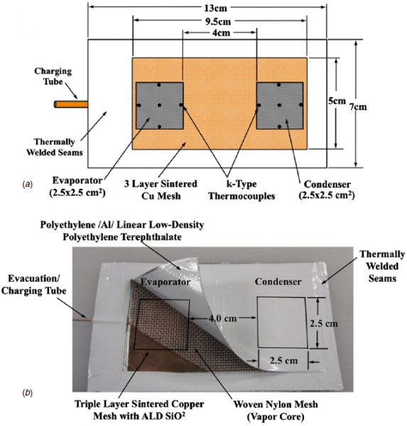
figure 3. (a) layout of the fphp; (b) cut-away view of the assembled fphp [4]
oshman et al. [4] fabricated and tested a flat, flexible polymer heat pipe (fphp); see figure 3. the overall geometry of the heat pipe was 130 mm × 70 mm × 1.31 mm. a commercially available, low-cost film composed of laminated sheets of low-density polyethylene terephthalate, aluminum and polyethylene layers was used as the heat pipe case. a triple-layer, sintered copper woven mesh served as the wick structure, and water was used as working fluid. a coarse nylon woven mesh provided space for vapor transport and mechanical rigidity. the thermal resistance of the fphp ranged from 1.2 to 3.0 °c/w depending on the operating conditions.
amec thermasol from united kingdom [5] manufactures a thin flat heat pipe product called “flat cool pipes”, which are flat aluminum heat pipes with acetone as the working fluid. please see figure 4. the flat heat pipe can be made as thin as 1.2 mm and is bendable. for 1.2 mm flat cool pipes, amec thermasol shows it has a thermal resistance of 0.4 °c/w and can transfer 5 watts of power in the horizontal orientation.

figure 4. flat aluminum heat pipe [5]
furukawa electric company from japan developed two different thin flat heat pipes. one commercial product is called pera-flex [6; see figure 5. the pera-flex heat pipe has an envelope-shaped container made of thin metal foil. its inner structure is illustrated in figure 6. a small amount of water is used as a working fluid inside the heat pipe. the pera-flex heat pipe can be fabricated as thin as 0.55 mm. their tests showed that the pera-flex heat pipe has a thermal resistance of 1.0 °c/w and can transfer a maximum 15 watts power.
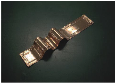
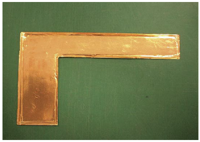
figure 5. pera-flex heat pipe: straight (left) and asymmetrical sharp (right) [6]
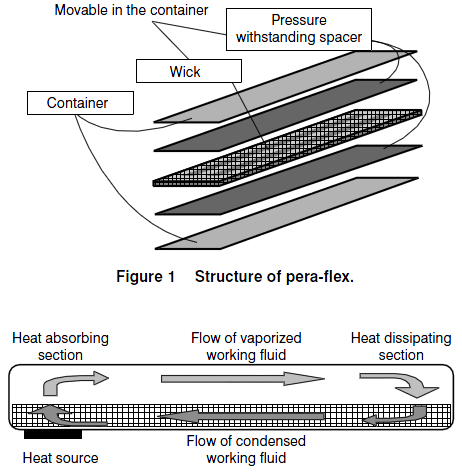
figure 6. pera-flex heat pipe structure [6]
the second type of thin flat heat pipe [7] that furukawa electric company developed is manufactured from a traditional round heat pipe, per figure 7. in this figure, both heat pipes were made from a round copper pipe of 6 mm diameter and flattened to their thickness. the width of the thin heat pipe is about 9 mm. the length of the 1.0 mm thickness heat pipe is 150 mm and that of the 0.7 mm thickness heat pipe is 100 mm, respectively. the flat heat pipes use meshed copper as the wick structure and water as the working fluid. to maximize the heat pipe performance and capillary force inside the wick structure, the researchers from furukawa electric company, aoki et al., used a process called oxidation-reduction to treat the copper mesh. they then compared the thermal performance of the heat pipes using common sintered wick, reduction treated mesh and oxidation-reduction treated mesh.
figure 8 shows the comparison of meshes after different processes. the surface of mesh wire becomes rough and the diameter of the wire expanded after the oxidation-reduction process. the wetting between the water and the wire surface will be increased due to the increase of the roughness of the wire. thus, the oxidation-reduction process can yield a high capillary pressure head.

figure 7. thin flat heat pipes [7]

figure 8. comparison of mesh wick surfaces a) reduction only b) oxidation-reduction [7]
aoki et al. tested different heat pipes by using the experimental setup illustrated in figure 9. they measured the temperature distribution of the heat pipe at different powers, by fixing the temperature of the adiabatic section. the experimental data for three 1.0 mm flat heat pipes are displayed in figure 10. the thermal performance of the heat pipes is almost the same between the sintered wick and the mesh wick with the reduction process. the maximum heat transfer capacity of these heat pipes is about 10 watts. the heat pipe which consists of the mesh wick with the oxidation-reduction process has a maximum heat transfer capacity of 22 w, which is much larger than that of the sintered wick and the mesh wick with only the reduction process.
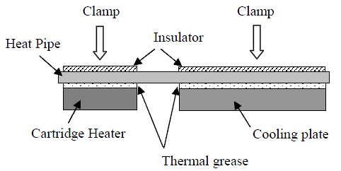
figure 9. schematic of experimental setup [7]
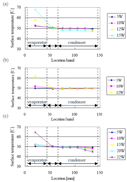
figure 10. temperature distribution of 1 mm thickness heat pipes. (a) common sintered wick, (b) mesh wick with reduction process, (c) mesh wick with oxidation-reduction process [7]
figure 11 shows the calculated thermal resistance between the evaporation and the condensation sections. the heat pipe with the oxidation-reduction process can transfer a maximum 22 watts of power and has the lowest thermal resistance of 0.2 °c/w.
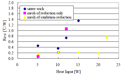
figure 11. thermal resistance of 1 mm thickness heat pipes [7]
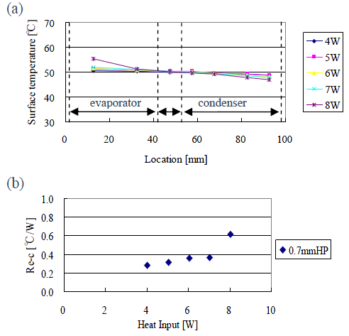
figure 12. thermal performance of 0.7 mm thickness heat pipe with oxidation-reduction process. a) temperature distribution; b) thermal resistance [7]
for the 0.7 mm thickness, the heat pipe with the sintered wick and the heat pipe with the reduction process mesh wick did not function normally in experiments because the pressure balance in the heat pipe collapsed. figure 12 shows the temperature distribution and calculated thermal resistance for the 0.7 mm thick heat pipe with the oxidation-reduction process. it can dissipate maximum 8 watts of power and has an average thermal resistance of 0.3 °c/w, which is 50% higher than that of the 1 mm thick heat pipe.
cooler master from taiwan also makes thin flat heat pipes [8]. their heat pipes use copper as a container and sintered copper as the wick structure. the working fluid is water. figure 13 shows one of the wick structures cooler master uses. cooler master is able to make this type of heat pipe as thin as 1.2 mm. figure 14 shows the finished 1.2 mm thick 200 mm long flat heat. figure 15 displays its thermal performance. it can transfer maximum 18 watts of power and its thermal resistance is around 0.15 °c/w when the power is less than 17 watts.
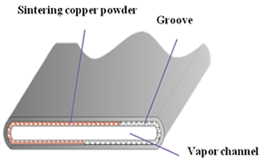
figure 13. flat heat pipe wick structure [8]
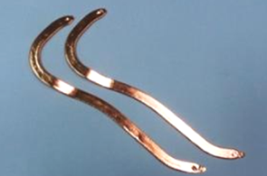
figure 14. 1.2 mm thickness flat heat pipe (200 mm length) [8]
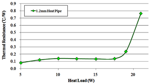
figure 15. thermal performance of 1.2 mm thickness flat heat pipe [8]
cooler master also developed another sintered wick structure for thin flat heat pipe, see figure 16. this wick structure only lines the inner wall of the heat pipe partly instead of the whole inner wall. for this kind of structure, cooler master can make flat heat pipe as thin as 1 mm. figure 17 shows the finished 1.2 mm thick 150 mm long flat heat pipes. figure 18 displays it thermal performance. it can transfer a maximum 26 watts of power with a thermal resistance of around 0.35 °c/w. when power is less than 17 watts, its thermal resistance is around 0.1 °c/w.
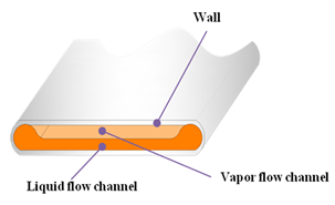
figure 16. flat heat pipe wick structure [8]
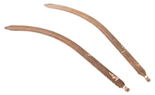
figure 17. 1 mm thickness flat heat pipe (150 mm length) [8]
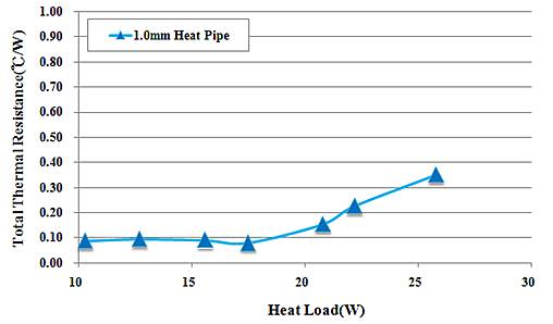
figure 18. thermal performance of 1 mm thickness flat heat pipe [8]
the above summary of the thin heat pipes shows that their thermal performance varies depending on their design, material used, wick structure and working fluid chosen. however, it also demonstrates that thin flat heat pipes fabricated by using traditional methods and innovative wick structure can achieve acceptable performances. for example, the 1 mm copper flat heat pipe produced by furukawa electric company can dissipate 22 watts of power and has a thermal resistance of 0.2 °c/w while the 1 mm copper flat heat pipe made by cooler master can dissipate 26 watts of power and has a thermal resistance of 0.1 °c/w. these flat heat pipes can be made even thinner. however, their performance will decrease as the heat pipe cross-section becomes smaller. as much as their performance for the thin dimension is attractive, it is highly recommended that they are tested in the in-situ conditions, as final performance may be impacted by the system deployment.
references:
- http://www.lightstreamphotonics.com/technology.htm
- david, r. and peter, k., heat pipes: theory: design and application, butterworth-heinemann, usa, fifth edition 2006.
- 3. le berre, m., launay, s., sartre, v., lallemand, m., “fabrication and experimental investigation of silicon micro heat pipes for cooling electronics,” journal of micromechanical engineering, vol. 13, pp. 436-441, 2003.
- 4. oshman, c., li, q., liew l., yang, r., bright, m. v., lee, y., “flat flexible polymer heat pipes”, j. micromech. microeng. 23 (2013) 015001 (6pp).
- 5. http://www.amecthermasol.co.uk/product412.php?url=1&page=282&ty=30&gr=30&fg=148
- 6. http://www.furukawa.co.jp/review/fr025/fr25_14.pdf
- 7. aoki, h., shioya, n., ikeda, m., kimura, y., “development of ultra thin plate-type heat pipe with less than 1 mm thickness”, 26th ieee semi-therm symposium, santa clara, ca usa, february 21-25, 2010.
- 8. http://odm.coolermaster.com/solution.php?page_id=23
to download a pdf of this article from coolingzone media sponsor qpedia, click https://www.coolingzone.com/blog/wp-content/uploads/2016/09/qpedia_may13_thermal_performance_of_thin_flat_heat_pipes.pdf.
|