|
introduction
telecommunication satellites are all based on the same overall design using a 3 axis stabilization process, in which the north and south panels act as radiators and so ensure heat removal.
this basic principle is illustrated in figure 1. the ever-increasing demand for national and international space-based communications in parallel with the evolution of space electronics (miniaturization, complexity, integration) dictate that the thermal control subsystem (tcs) can accommodate significant increases in spacecraft dimensions and waste heat generation. at the same time, for obvious economic reasons, the operational life time in orbit has to reach 15 years for most satellite programs.

figure 1: thermal design of geostationary satellites.
methodology
space programs, generally limited to very few models characterized by high cost (typically $50,000-100,000/kg), must follow a specific methodology. the main design features of this methodology are:
- the tcs design has traditionally been a conservative process. use of previously flown materials, technology and concepts is encouraged.
- the design is mainly based on an important use of analytical models (see figure 2). the simulation is achieved by using cad software (catia) as a mesh generator and esatan (european agency thermal analysis) as a thermal solver. mock up and thermal tests are considered for final verification.
- assumptions obtained by thermal modeling are a possible source of errors, thus uncertainty margins (typically ±5°c) are taken into account by thermal designers in order to make "guaranteed predictions".
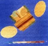
figure 2 - thermal map of a geostationary satellite.
electronic equipment temperature limits and design
a spacecraft contains many components which will function properly only if they are maintained within specified temperature ranges. figure 3 illustrates a classical set of temperature limits for on board equipment.
| equipment |
on-orbit temperature range (°c) |
qualification range (°c) |
| minimum during non operating phase |
operating |
operating |
| electronic units |
|
min |
max |
min |
max |
| " |
twt (traveling wave tubes) |
-30 |
0 |
+75 |
-10 |
+85 |
| " |
electronic power conditioner |
-30 |
0 |
+50 |
-10 |
+60 |
| " |
input filters |
-30 |
+5 |
+50 |
-5 |
+60 |
| " |
microwave equipment (transponders, receivers, ) |
-30 |
-10 |
+50 |
-20 |
+60 |
| " |
output multiplexers |
-30 |
+20 |
70 |
+10 |
+80 |
| " |
data processing units |
-30 |
-10 |
+50 |
-20 |
+60 |
| " |
ir and sun sensors |
-45 |
-30 |
+50 |
-40 |
+60 |
| " |
battery ni-h2 |
-20 |
-5 |
+25 |
-15 |
+35 |
| non-electronic units |
tanks |
0 |
0 |
40 |
-10 |
50 |
| solar generator |
-180 |
-165 |
+70 |
-175 |
+80 |
| propellant lines |
0 |
05 |
0 |
-10 |
+60 |
| momentum wheels |
-40 |
-15 |
45 |
-25 |
+55 |
figure 3 - temperature limits for on-board equipment.
in order to meet the challenge of the increasing complexity of communication satellite payloads, the packaging of space electronic equipment must minimize the imposition of severe constraints on electronic designers.
from a reliability point of view, the fundamental goal of tcs is to ensure a maximum junction temperature of 110°c; therefore, printed circuit boards with high thermal conductivity are used in conjunction with local heat spreaders. in some critical areas, heat pipes are used to provide efficient and low mass technical solutions.
an overall view of the implementation of electronic equipment inside a telecommunication satellite is illustrated in figure 4.
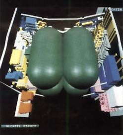
figure 4 - cad illustration of telecom 2 satellite.
radiators
the radiators use primary heat rejection surfaces:
- they support high dissipating electronic units (traveling wave tubes and converters). the structural composition of these panels is generally aluminum face sheet and honeycomb core.
- they are designed for a maximum thermal efficiency achieved by using embedded heat pipes in association with a specific coating providing a high infrared emittance with a low solar absorptance (so called optical solar reflectors). for end of life conditions, heat rejection capability may reach up to 350 w/m2 for a typical 40°c radiator temperature.
a concept of a flexible radiator, acting as a 'thermal diode', which allows heat to pass from an internal to external side has been designed and successfully qualified by alcatel espace to reduce tcs weight for low earth orbit missions.
heat pipes
the vast majority of heat-pipe applications use an axially grooved aluminum/ammonia constant conductance heat pipe (cchp) (see figure 5). successful ground testing and flight experiences indicate cchp to be a reliable thermal control element.
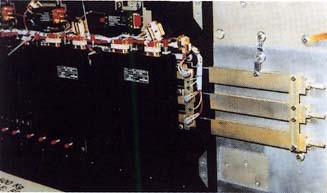
figure 5 - constant conductance heat-pipes (cchp) fixed on a panel support structure.
non condensable gas generation caused by impurities is controllable by the manufacturers process.
liquid slug formation in zero gravity still remains a problem and is taken into account during cchp layout on the spacecraft panels.
insulation design
with the exception of the radiator areas used for heat rejection, a satellite is covered by a blanket of multi layer insulation (mli) intended for protection from solar flux and to protect surfaces submitted to large diurnal environmental fluctuations -180°c up to +150°c.
mli design consists basically of a number of layers of vapor-deposited aluminum, silver or gold on kapton or mylar. conductive insulation between layers is insured by interleaved fabric netting.
another important requirement for mli design is to provide an efficient protection against electro static discharge (esd), which may appear between separated parts when formed from different materials or submitted to sunlight or shadow.
heaters
thermal control of electronic equipment within a narrow range of temperature (ambient ±20°c), with external surface temperature differences ranging from -180°c up to + 150°c, is generally achieved with the help of active heaters controlled by mechanical thermostats or on-board computers. heating elements are generally thermofoil conductive electrical elements embedded in a thin kapton substrate.
a thermal vacuum test environment with solar simulation is essential for verification of the thermal mathematical models and tcs performances in a simulated orbital environment.
solar heat fluxes are simulated by a set of xenon lamps which illuminate the spacecraft by focusing into a single collimated beam.
these huge test facilities are only available in a few locations in the world: interspace in toulouse has a facility (see figure 6), which includes other environmental tests (mechanical, emc), thus permitting a certification of "flight aptitude" for spacecraft before launch.
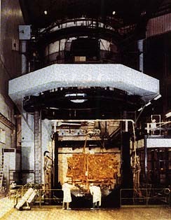
figure 6 - thermal test chamber: 600 m3 vacuum: 10 -6 mmhg temperature: -170°c up to 120°c.
conclusion
the continued strong growth in communication satellite requirements has resulted in a need for more complex satellites which must be delivered in the shortest time possible.
tcs designers will be required to enhance flight-proven technologies, while developing new techniques such as fluid loops and micro heat-pipes.
patrick zemlianoy
head of design for space environment and methodology
alcatel espace
charles combes
manager, thermal design office
alcatel espace
references:
1. techniques et technologies des v hicules spatiaux (cnes), cepadues satellite communication system engineering, w.l .pritchard, j.a. sciulli, prentice hall.
2. thermal analysis and control of electronic equipment, a.d. krauss, a. bar-cohen, mcgraw-hill.
|


