|
introduction
fiber optic temperature measurement has been in use for decades1. the most prevalent methods are fluorescent and radiation thermometry, also known as pyrometry. fluorescent temperature measurement is used for lower-range measurements from -200°c to +450°c. pyrometry best covers ranges from 100°c to 4,000°c, and is based on the physics of planck's blackbody radiation equation2.
as higher quality in products and tighter process control become critical, so does the production use of sapphire fiber optic temperature measurement. the in-situ use of sapphire lightpipes to collect hot-object-emission is becoming the industry standard for many industrial processes. companies such as eaton, dupont, corning glass, lucent technologies, ibm, and intel all use this technology. equipment companies and furnace vendors are implementing lightpipes and fiber optic temperature measurement systems in semiconductor, glass, aerospace, and materials processes.
fiber optics afford greater design flexibility, and provide the capability to create a virtual blackbody environment. they also have several advantages over thermocouples: low noise, about 1000 times better; high resolution, 0.01°c; high speed and fast response, enabling up to 20,000 measurements per second; and non-contact operation - a must for the semiconductor industry.
basics of fiber optic pyrometry
fiber optic radiation thermometry is composed of the collection optics (sapphire lightpipes or lens), optical transmission cable, optical-to-electrical conversion (photodetector), and signal processing (fig. 1). generally, the collection optics is a rod or flexible fiber of sapphire directed at the hot object. the lightpipe is placed so as to create increased emissivity, such as a small hole through a holder or by placing a mirror close to the hot object1,3,4,5. sometimes a lens assembly is used instead of the sapphire and the optical signal is taken to the electronics through optical transmission cable.
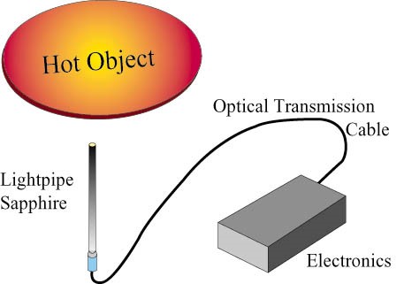
fig. 1 - typical fiber optic system for temperature measurement.
small and large signals
a typical output from a photodetector can change nine orders of magnitude (1,000,000,000 times) over an input range from 200°c to 1200°c. in figure 2, the steepness of the curve at low temperatures should be noted, showing a large change in current for a small change in temperature. this means that the available signal is dropping off very quickly at these lower temperatures. this is often referred to as a _cliff._ the way the photodiode output is handled determines the temperature range and system performance. historically, the _best_ signal amplification has been a trans-impedance amplifier6. this amplifier approach has a lower temperature limit defined by shot and johnson noise. shot noise arises from the statistical fluctuation in the current; johnson noise originates mainly from the amplifier's feedback resistor.
another approach uses an integrating amplifier. the feedback resistor can be considered as being replaced by the equivalent of an integrating capacitor. there are two basic advantages to the integrating amplifier approach: there is no longer the electrical noise associated with the feedback resistor on the first stage gain, and the integrating amplifier measures photons for a longer time period (integrates) and is more sensitive to low light levels. the lowest temperature capable of being measured at 1-µm wavelengths, using the trans-impedance amplifier, is about 300°c, with 1°c resolution. a cooled integrating amplifier can measure to about 200°c using 1-µm wavelength light.
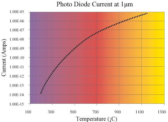
fig. 2 - photodiode current at 1µm wavelength.
measurement problems
unknown emissivity is always the most serious problem with any pyrometric temperature measurement. it can cause very large errors (see table). generally, errors are always larger for longer wavelengths and higher temperatures. there is a myth in pyrometry, that by using two wavelengths the emissivity problem is solved. although it is true that if emissivity is the same at both wavelengths or changes by the same rate, the ratio of intensities will yield temperature from the planck equation. however, emissivity rarely changes the same at both wavelengths as a part is heated or processed.
| pyrometric measurement error associated with an emissivity error of 0.2 (0.7 to 0.9) |
| object temperature |
wavelength |
error |
| 500°c |
1µm |
10°c |
| |
3µm |
27°c |
| 1000°c |
1µm |
27°c |
| |
3µm |
73°c |
real-life emissivities range from 0.1 (aluminum) to over 0.95 (graphite) and everything in-between1,3. emissivity is also dependent on surface films and the angle of emission. unless a pseudo or virtual blackbody is formed - or the ripple technique employed - the error can be large.
ripple technique
the use of the time-dependent component of background light to determine real time emissivity was first presented as the "ripple technique" 7,8. it takes advantage of the fluctuating nature of a background light source to determine the amount of light reflected off any hot sample. the 60-hz ac line frequency of lights can be used as the fluctuating background light. the reflectivity of any sample is the ratio of the incoming ac light to the reflection of that ac light signal off the hot sample. given the view angle of the lightpipe the emissivity is one minus reflectivity or:
emissivity = 1 - δis / δib
where  ib is the ac component of the background light, and δis is the background light's ac component reflected from the hot sample. ib is the ac component of the background light, and δis is the background light's ac component reflected from the hot sample.
conclusions
temperature measurement using optical fibers and wavelengths under 1µm, continues gaining widespread acceptance. the shorter wavelength gives a smaller emissivity error. for optimum measurement and control the combination of the sapphire fiber, low noise circuitry, and the ripple technique yield the best non-contact temperature measurements. currently the best multi-point temperature measurement system measures from 100°c to 2000°, with a resolution of 0.01°c at 80hz, using short wavelength light.
the use of sapphire lightpipes will continue gaining acceptance for all types of applications in industry and science. at least a dozen equipment manufacturers now use lightpipes for in-situ temperature measurements, and more than 10,000 optical fiber-based temperature systems have been sold.
chuck schietinger,
luxtron corp.
santa clara, calif.
references:
1. d.p. dewitt, theory and practice of radiation thermometry, edited by d.p. dewitt and g.d. nutter, wiley, new york, (1988).
2. m. planck, annals of physics, 4 (3), 553, (1901)
3. c. schietinger, chapter 3 and 4 in advances in rapid thermal and integrated processing, edited by f. roozeboom, kluwer academic publishers, dordrecht, the netherlands, 1996.
4. christian m. gronet and gary e. miner, european patent application publication no. 612 862, (24 jan. 1994).
5. p. vandenabeele and k. maex, j. vac. sci. technol. b, 9, 2784-2787 (1991).
6. c. schietinger, e. jensen, mater. res. soc. symp. proc. spring meeting san francisco 1996.
7. c. schietinger, b. adams and c. yarling, mater. res. soc. symp. proc. 224, (1991) pp. 23-31.
8. c. schietinger and b. adams, u.s. patents 5,154,512 (13 oct. 1992), 5,166,080 (24 nov. 1992), 5,310,260 (10 may 1994), 5,318,362 (7 june 1994), 5,490,728 (13 feb. 1996).
|


