|
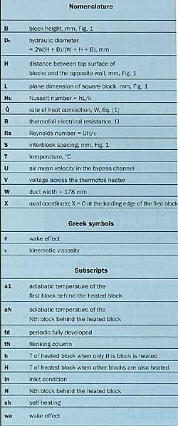
introduction
an earlier work by the authors (molki et al., 1995) discussed the adiabatic heat transfer coefficient of rectangular blocks situated in an in-line array. in real circuit boards, heat is generated by a number of electronic components. the temperature of each component is affected by two factors, self-heating and thermal wake effect. self-heating is the temperature rise due to heat generated within the component, while thermal wake effect is the heating caused by the thermal wake of the upstream heated components.
the purpose of this article is to indicate how the adiabatic heat transfer coefficient can be employed to predict the temperature of the components simulated by an in-line array of rectangular blocks with random heating. the focus of the work is on the entrance heat transfer coefficient, which has more practical application. pressure drop results have also been obtained and reported elsewhere (molki et al., 1994).
review of the literature
heat transfer in arrays of rectangular blocks has been addressed by a number of investigators. sparrow et al. (1982, 1983) reported adiabatic heat transfer coefficients in arrays of rectangular blocks with barriers and missing blocks. arvizu and moffat (1982) discussed a superposition approach for predicting the temperature of a regular array of cubical elements. wirtz and dykshoorn (1984) studied heat transfer in a sparse array of elements. in a series of experimental investigations, moffat and his group have extensively studied thermal-hydraulic behavior of the arrays of electronic components (moffat et al., 1985, moffat and anderson, 1998, anderson and moffat, 1990, 1991). other relevant studies are those reported by faghri et al. (1991), a review by peterson and ortega (1990), anderson (1997), and leung and kang (1998).
the experimental setup and procedure
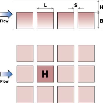
the experimental setup consists of a bell-mouth inlet, a flow development section (591 mm), a test section (343 mm), a flow redevelopment section (591 mm), a venturimeter, a control valve, and a blower. the copper rectangular blocks are positioned along the lower wall of the test section in an in-line arrangement. the geometry of the test section is identified with s, h, l, and b. in this study, the range of parameters was s = 6.4 - 8.4 mm, h = 6.4 - 25.4 mm, l = 25.4 - 49.8 mm, and b = 12.7 - 25.4 mm, corresponding to s/l = 0.128 - 0.33, h/l = 0.128 - 1, and b/l = 0.5.
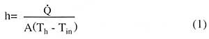
in a typical data run, only one copper block was heated at a time, and the remaining blocks were adiabatic. the input power was adjusted such that the temperature difference between the block and ambient remained constant (30°to 50°c). the convective heat transfer coefficient is evaluated from:
where q is calculated as heat generated by the heater, v2 /r, minus the conduction and radiation heat losses. conduction losses were evaluated from a numerical simulation of heat transfer in the copper block and the adjacent walls. radiation losses were estimated from a simplified model where the heated block is treated as a small radiating object surrounded by a large environment. it was found that conduction and radiation losses were 10% and 1% of v2/r , respectively.
temperature prediction
the data reported earlier by the authors (molki et al., 1995) included details of the adiabatic heat transfer coefficients in the entrance and fully-developed regions of the in-line array of rectangular blocks. the focus of this article, however, is on correlations obtained from the earlier data.
figure 1. schematic view of the array of blocks.
adiabatic heat transfer coefficient
in fig. 1, the heated block is marked "h," while the remaining blocks are adiabatic. when only one block is heated, as in fig. 1, the heat transfer coefficient obtained from eq. (1) is the adiabatic heat transfer coefficient. based on the present experimental data, the fully-developed adiabatic heat transfer coefficient is obtained from:
|
nufd = 0.343re0.607 (s/l)0.295 (h/l)-0.670
|
(2)
|
where nufd =hl/k. the entrance (developing) adiabatic heat transfer coefficient is a function of the axial distance, x, and is expressed as:
|
nu/nufd = 1+0.0786(x/dh)-1.099
|
(3)
|
equations (2) - (3) are suggested as a complete set of correlations for the adiabatic heat transfer coefficient.
adiabatic temperatures
temperature of the heated block (when only one block is heated), th, is obtained from eq. (1). the temperature of the adiabatic block situated immediately downstream of the heated blocks is obtained from"
|
|
(4)
|
where θ1=(ta1-tin )/(th -tin ). temperatures of the 2nd and subsequent blocks situated downstream of the heated block are expressed as:
|
θn/θ1=0.151+0.849n -1.314
|
(5)
|
in this equation, n equals 2, 3, ., for 2nd, 3rd, ., blocks situated downstream of the heated block, respectively. these downstream adiabatic blocks are sitting in the thermal wake of the heated block and are heated by the heat generated upstream. the blocks in the flanking columns are also affected by the thermal wake of the heated block. the wake effect for the flanking column may be represented by:
|
θn/θ1=0.151+0.849n-1.314
|
(6)
|
the subscript fn indicates the nth block of the flanking column. in this model, it is assumed that the blocks of the columns situated farther away from the flanking columns are not affected by the thermal wake of the heated block.
operating temperatures of the blocks
the operating temperatures of an in-line array of blocks with random heating can be found from superposition of temperatures (arvizu and moffat, 1982). in this procedure, the temperature of each block is considered to have two components. one is self heating, δtsh = th-ta=th-tin, the other is due to the thermal wake of the upstream heated blocks, δtwe = ta-tin= σ (ta,i-tin) . the upstream blocks include the heated blocks in the same column and those situated in the flanking columns. therefore, the operating temperature of a block of array is th = tin +δtsh+δtwe. in these equations, ta,i is the adiabatic temperature of the block due to the thermal wake effect of the ith upstream heated block.
the algorithm is started by providing the geometric parameters (number of rows and columns, l, b, s, h, w), air inlet velocity, uin, inlet air temperature, tin , and power dissipation in each block. these values are used to obtain s/l, h/l, x/dh, and re. then, the operating temperatures are computed as follows:
1. adiabatic heat transfer coefficient, h, is obtained from eq. (2) - (3) for all blocks of the array.
2. temperatures th are found for all blocks of the array from (power - heat losses) = ha(th - tin). this is the temperature when only one block is heated. then, the self-heating component of temperature rise is calculated from
δtsh = th-ta =th-tin.
3. thermal wake effect for each block is determined as follows:
a) for the first row, there is no thermal wake effect, and t h = th.
b) for the second and subsequent rows, the wake effect caused by the upstream heated blocks in the same row and flanking rows is calculated from eqs. (4) - (6). thermal wake effect for each block is δtwe = ta-tin= σ (ta,i-tin).
4. finally, the operating temperature of the block is found from
t h = tin+δtsh+ twe.
in the next section, the temperature of a randomly heated array of blocks is predicted by the above procedure.
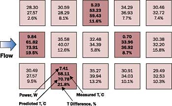
figure 2. a typical temperature distribution.
application example
an example is shown in fig. 2. the blocks that have four numbers written on them are heated, while the remaining blocks are adiabatic. the first of the four numbers on the heated blocks is the power generated in watts. the last three numbers on the heated and unheated blocks indicate the measured and computed temperatures, and their difference, respectively.
these predictions were made for l = 49.8 mm, b = 25.4 mm, s = 6.4 mm, h = 38.1 mm, uin = 1.24 m/s, and t in = 27.57°c, with s/l = 0.128, h/l = 0.765, b/l = 0.5, re = 5000. as seen, the difference between experiment and prediction is in the range of 2.6 to 21.8 percent, and the mean difference is 11.0 percent.
conclusions
the authors have presented a method to predict the operating temperature of an in-line array of heated blocks from adiabatic heat transfer coefficients and thermal wake effects. a sample calculation indicated that the temperature difference between experiment and prediction was 2.6 to 21.8 percent, and the mean difference was 11.0 percent.
however, since the real electronic components are irregular both in placement and size, the model presented in this paper may not be applicable to highly irregular layouts. moreover, the present approach apply to air-cooling and are limited to the range s/l = 0.128 - 0.33, h/l = 0.128 - 1, b/l = 0.5, and re = 3,000 - 15,000.
majid molki, ph.d.
department of mechanical engineering
university of maryland
college park, maryland
mohammad faghri, ph.d.
department of mechanical engineering and applied mechanics
university of rhode island
kingston, rhode island
references
1anderson, a.m., 1997, "comparison of computational and experimental results for flow and heat transfer from an array of heated blocks," journal of electronic packaging, transactions of the asme, vol. 119, pp. 32-39.
2.anderson, a. m., and moffat, r. j., 1990, "a new type of heat transfer correlation for air cooling of regular arrays of electronic components," proceedings of asme winter annual meeting, pp. 27-39.
3. anderson, a. m., and moffat, r. j., 1991, "direct air cooling of electronic components: reducing component temperatures by controlled thermal mixing," asme journal of heat transfer, vol. 113, pp. 56-62.
4. arvizu, d. e., and moffat, r. j., 1982, "the use of superposition in calculating cooling requirements for circuit board mounted electronic components," proceedings of the 32nd electronic components conference, ieee, vol. 32, pp. 133-144.
5.faghri, m., ray, a., and sridhar, s., 1991, "entrance heat transfer correlation for air cooling of arrays of rectangular blocks," heat transfer enhancement in electronics cooling, asme htd-vol. 183, pp. 19-23.
6.leung, c. w., and kang, h. j., 1998, "convective heat transfer from simulated air-cooled printed-circuit board assembly on horizontal or vertical orientation," international communications in heat and mass transfer, vol. 25, no. 1, pp. 67-80.
7.moffat, r. j., arvizu, d. e., and ortega, a., 1985, "cooling electronic components: forced convection experiments with an air-cooled array," heat transfer in electronic equipment, asme htd-vol. 48, pp. 17-27.
8.moffat, r. j., and anderson, a. m., 1988, "applying heat transfer coefficient data to electronics cooling," presented at the asme winter annual meeting, chicago, il.
9.molki, m., faghri, m., and ozbay, o., 1995, " a correlation for heat transfer and wake effect in the entrance region of an in-line array of rectangular blocks simulating electronic components," asme journal of heat transfer, vol. 117, pp. 40-46.
10.molki, m., faghri, m., and ozbay, o., 1994, "a new correlation for pressure drop in arrays of rectangular blocks in air-cooled electronic units," asme journal of fluids engineering, vol. 116, pp. 856-861.
11.peterson, g. p., and ortega, a., 1990, "thermal control of electronic equipment," in: advances in heat transfer, vol. 20, pp. 181-305.
12.sparrow, e. m., niethammer, j. e., and chaboki, a., 1982, "heat transfer and pressure drop characteristics of arrays of rectangular modules encountered in electronic equipment," international journal of heat and mass transfer, vol. 25, pp. 961-973.
13.sparrow, e. m., vemuri, s. b., and kadle, d. s., 1983, "entrance and local heat transfer, pressure drop, and flow visualization for arrays of block-like electronic components," international journal of heat and mass transfer, vol. 26, pp. 689-699.
14.wirtz, r. a., and dykshoorn, p., 1984, "heat transfer from arrays of flat packs in a channel flow," proceedings of the fourth annual international electronics packaging society, baltimore, md, pp. 247-256
|