|
air velocity is a parameter that often is referenced in thermal design. yet there is surprisingly little written about its definition. it could be that velocity is regarded as something so evident that it need not be discussed.
this article will, however, reveal that there are several definition problems and that overlooking these can cause significant errors.

figure 1 - velocity profile development between parallel plates.
the problem
any fluid that enters a channel undergoes quite a change on its way downstream, see figure 1. it is evident that the only exact way to characterize such a flow is as velocity field. that type of specification is, of course, complex but computers can easily manage this problem. what is more problematic, however, is the limit of the human mind to interpret large volumes of data.
it takes time to deduce something useful from a large collection of numbers. flow visualization are helpful but they are not easily accessible. regardless of how much advances are made in computer technology there will always be a need for comprehensive velocity values.
another aspect is that almost all classical heat transfer correlations require that the flow pattern is represented by a single parameter, the air velocity.
basic definitions
comprehensive air velocity values are used for several different purposes. because a single velocity value is a simplification of very complex phenomena, it is not possible to use one single definition for all of them. there are at least three basic definitions.
1. local velocity
2. linear average velocity
3. quadratic average velocity
the local velocity is classically used for boundary layer calculations. lately it has also found a wide spread use in cfd programs. this velocity is somewhat difficult to measure. the sensors must be small and positioned with high accuracy. an array of local velocity values measured in a cross section can also be used to calculate the average velocity. some 25 measuring points across a channel are needed for a high precision result.
the linear average velocity is important because it is used as a reference value in classical heat transfer theory. it is usually referred to as “average velocity” or just “velocity”. this is because it is used so often that it has become a default definition. it is defined as the ratio of a volumetric flow and a cross section.
this definition is seemingly simple but in enclosures for electronics and particularly in the air gaps between pcbs, it is not evident how the cross section should be defined.
since the linear average velocity is defined by an equation it can only be measured indirectly. there are two basic methods. it can be measured as a volumetric flow linked with an appropriate cross section or it can be measured as an average value of several local readings.
the quadratic average velocity is used to calculate the kinetic energy in a flow. the linear average and the square average velocities have the same value only if the velocity profile is uniform. if not, the latter is higher than the former.
for nice fully developed velocity profiles the difference is a few percent but for the type of distorted velocity profiles that so often occur in electronics, it can be quite substantial. the bernoulli equation, which works reasonably well for calculations in air conditioning systems, is therefore highly approximate when applied to flow in electronic enclosures.
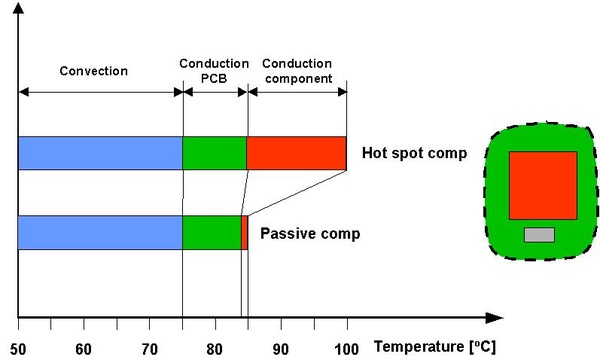
figure 2 - temperature conditions for a hot spot and an adjacent passive component.
how important is air velocity
before discussing velocity definitions more in detail it is essential to have a rough perception of its importance. a thermal situation that not is uncommon is shown in figure 2. a hot component has an adjacent component that is almost passive. both components are classified as industrial grade; that is, they are guarantied to function safely up to 85 °c ambient air temperature.
the safe function chip temperature for the hot component is assumed to be 100 °c. the corresponding limit for the passive component is evidently 85 °c.
the hot component pushes the major part of its heat out on the circuit board. this heat has to overcome three thermal barriers, conduction inside the component, conduction in the pcb and convection on the pcb surface. figure 2 shows how the corresponding temperature differences typically will be distributed.
the passive component is located close to the hot component. although the former dissipates little heat, it senses the pcb temperature that is generated by the hot component. both components, therefore, operate on their critical upper specification limit. table 1 shows how the available temperature differences are used.
-
|
mode
|
hot [%]
|
passive [%]
|
|
conduction in component
|
30
|
2
|
|
conduction on pcb
|
20
|
29
|
|
convection
|
50
|
69
|
table 1 - relative distribution of temperature differences for the components in figure 2.
the air velocity only has an impact on the convection part. a conclusion from the results in table 1 is that the air velocity is a more important parameter for the passive component than for hot component!

figure 3 - impact of a velocity error on the temperature difference error.
the correlation between convection and air velocity is not linear. it can locally be approximated as in figure 3. the exponent, n, can take values in the range 0.33 - 1.0. for forced convection at 1.5 m/s it is approximately 0.7. a 10% increase in air velocity will thus result in a 7% decrease of the temperature difference.
this may seem as poor pay off for the effort. on the other hand, it can also be argued that if the velocity happens to be lower than expected, this would not make that much harm. in other words, mother nature gives us a 30% discount on our errors.
when looking at the impact of a velocity error on the chip-to-air temperature difference the image changes somewhat. table 2 shows the chip level error, when the velocity error is 10%.
-
|
component
|
error [°c]
|
error [%]
|
|
hot spot
|
1.8
|
3.6
|
|
passive
|
1.8
|
5.1
|
table 2 - impact of a 10% velocity error on the chip temperature for the components in figure 2.
it can be concluded that the air velocity without doubt is an important factor but that velocity variations on the 10% level, or even higher, seems acceptable for most standard cases.

figure 4 - the velocity profile is deformed by components.
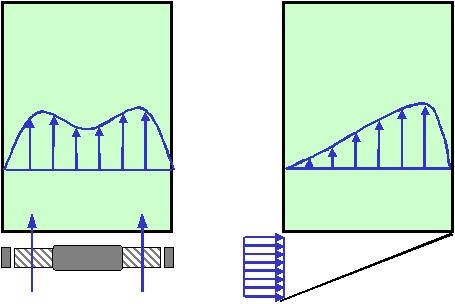
figure 5 - the velocity profile is highly dependent on the inlet condition.
velocity in pcb gaps
figure 4 shows how the velocity profile deforms when the airflow in a pcb gap encounters a component. viewed from the top, the situation is not much better. in this view there will also be deformations caused by components but the inlet condition is probably the factor that has the most drastic impact. figure 5 shows two examples.
a detailed discussion about the thermal consequences of these velocity profile deformations is outside the scope of this article. it is, nevertheless, a fact that the thermal conductivity of modern pcbs is so high that the impact is considerably neutralized.
it is apparent that it is impractical to define the velocity in pcb gaps with the velocity profile. the obvious alternative is to use an average value. some information is undoubtedly lost as a consequence of such a definition but it has on the other hand the advantage of being simple. figure 6 shows one velocity definition suggestion. there are many other alternatives and each has its advantages and disadvantages.
it is nevertheless important to apprehend that alternative definitions can result in discrepancies well above 10%. a velocity specification for a pcb is not complete unless it is linked with a definition.
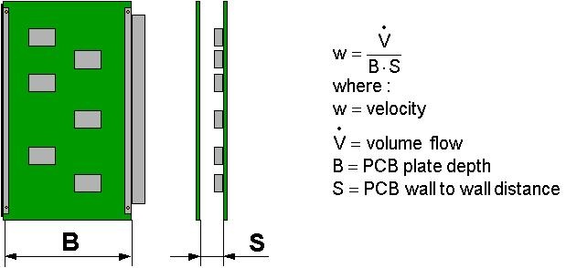
figure 6 - suggested definition for velocity in pcb gaps.
an important issue is whether the velocity definition in figure 6 can serve as a reference value for heat transfer coefficient calculations. this is certainly possible. for estimates it can be used “as is”. more accurate calculations will require the use of several correction factors.

figure 7 - confined and non-confined flow through a heat sink.
velocity for heat sinks
for heat sinks there are two distinct flow cases, confined and non-confined flow, see figure 7. for the non-confined flow case there is not much choice. the velocity must be specified as the average air velocity in the flow channel. such a specification is, however, not complete unless it is linked to a clarification of the by pass conditions.

figure 8 - suggested velocity definitions for heat sinks in confined flow.
for confined flow there is the problem of the bottom plate thickness. following the general principle outlined above, two definitions are possible, see figure 8. these definitions are here made for a heat sink with a relatively simple cross section but the definitions can easily be generalized.
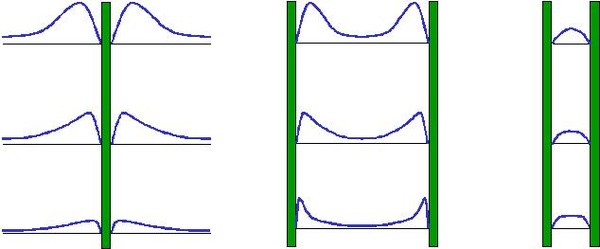
figure 9 - velocity profiles at natural convection.
equivalent velocity
the velocity definition for pcb gaps outlined above is convenient for most cases. some times, for example at natural convection, it is advantageous to use another approach. the equivalent velocity is defined as the velocity that results in the same heat transfer coefficient as if it the convection had been forced.
at natural convection and for small wall-to-wall distances this definition results in a velocity that equals the physical average definition, see figure 9. as the wall-to-wall distance increases the equivalent velocity becomes higher than the physical velocity. the wall-to-wall distance break point at which these two velocities not longer can be regarded as approximately equal is for 200 mm high pcbs about 30 mm.
the equivalent velocity is useful for cases in which the velocity is small and therefore difficult to measure. the definition also makes it possible to treat some natural convection cases as forced convection cases, which sometimes can facilitate calculations considerably.
velocity measurements
it is not difficult to measure the velocity in a single spot inside an electronic enclosure. modern hot wire anemometers have a good precision and their sensors are often so small that they only cause minor disturbances. the problem is that the velocity reading will differ considerably depending on where the sensor is placed. it is, therefore, not possible to get a good overview unless a large number of sensors are used.
an alternative technique is to measure the flow and then apply the definitions above. there are many flow measurement principles but none of them is general in the sense that it can be used for all situations. a thorough analysis of this subject would require many pages of explanations. there is, however, a method that is very little used and yet is both simple and often applicable, the heat balance.
the principle for the heat balance method is shown in figure 10. several matters make this method attractive. the heat dissipation can usually be electrically measured, modern temperature sensors are small and the instruments needed are simple. a particular difficulty with this method is that the heat and flow losses over the control volume borders must be carefully controlled. another difficulty is that the temperature distribution in the outlet air often is non-uniform.
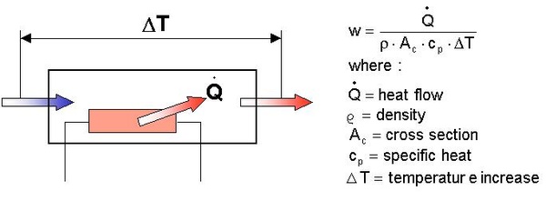
figure 10 - the heat balance principle.
how you should not measure the air velocity
making mistakes is an embarrassing but efficient way of learning. the story that follows is about how air velocity not should be measured.
the basic idea was to measure the velocity with the same method that is used by hot wire anemometers. these devices measure the temperature rise on a heated wire and transform that reading into a velocity through the means of a calibration curve. why use a small wire, why not an entire pcb and why not a heated aluminum plate?
a heated aluminum plate with several temperature sensors was prepared and placed in a sub rack. the calibration was made by connecting the sub rack to a wind tunnel equipped with an accurate flow meter. the curve achieved looked good and it could in addition be reproduced a few days later. when the sub rack was placed in its proper enclosure, this arrangement did produce highly erroneous velocities, why?
the problem was that the flow over the aluminum plate in this case happened to be in the intermediate zone between laminar and turbulent flow. all kinds of inlet flow disturbances, caused by fans or flow channel elbows, can therefore have a significant impact on the cooling. this problem was magnified by the fact that transforming temperature difference readings into air velocities increases the error rather than the other way around, see figure 3.
about ake malhammer

ake obtained his master of science degree in 1970 at kth, (royal school of technology), stockholm. he then continued his studies and financed them with various heat transfer-engineering activities such as deep freezing of hamburgers, nuclear power plant cooling and teaching. his ph.d. degree was awarded in 1986 with a thesis about frost growth on finned surfaces. since that year and until december 2000 he was employed at ericsson as a heat transfer expert. currently he is establishing himself as an independent consultant.
having one foot in the university world and the other in the industry, ake has dedicated himself to applying heat transfer theory to the requirements of the electronic industry. he has developed and considerably contributed to several front-end design methods, he holds several patents and he is regularly lecturing thermal design for electronics.
to read ake's website for more thermal information and software tools he has developed, visit http://akemalhammar.fr/.
|