|
a heat pipe is a device with very high thermal conductance that can transport large quantities of heat with small temperature difference between its hot and cold ends. it is normally used to transport heat from one area to another or to smooth the temperature distribution on a solid surface. heat pipes are widely used in aerospace applications, military devices, temperature control systems, and now in personal computers.
a heat pipe is a self-driven, two-phase device. a schematic view is shown in figure 1. at its hot end (evaporator) the liquid evaporates and turns to vapor. this vapor flows to the cold end (condenser) where it liquefies. the liquid is driven back from the cold end to the hot end by capillary forces within the heat pipe’s wick structure.
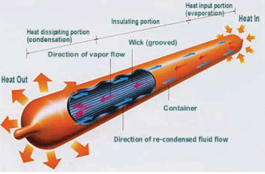
figure 1. typical heat pipe [1]
the heat transfer ability of a heat pipe is determined by its diameter, fluid type, wick structure, and orientation. the heat flux limitations of a heat pipe are governed by the following factors (figure 2):
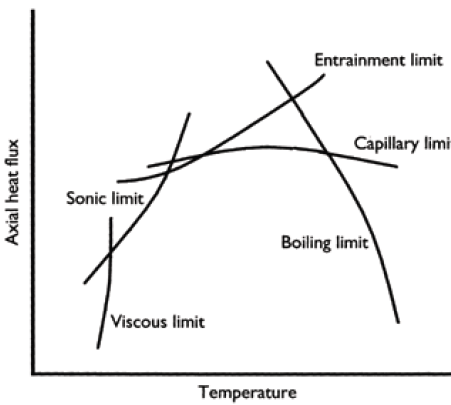
figure 2: limits to heat transfer in a heat pipe [2]
1) viscous limit. at low temperature, the vapor pressure difference between the evaporator and the condenser may not be enough to overcome viscous forces.
2) sonic limit. this occurs when the vapor velocity reaches sonic speed at the evaporator and any increase in the pressure difference will not speed up the flow.
3) entrainment limit. at high vapor velocities, droplets of liquid are torn from the wick and entrained in vapor. the droplets flow to the condenser with the vapor, which results in drying out on the evaporator.
4) capillary limit. this is reached when the capillary pressure is too low to transport enough liquid to the evaporator from the condenser.
5) boiling limit. when the radial heat flux into the heat pipe causes the liquid in the wick to boil and evaporate, which leads to heat pipe dry out.
for a heat pipe to operate, the capillary pumping power  must be greater than the total pressure drop in the must be greater than the total pressure drop in the
pipe. the total pressure drop is made up of three components [2]:
1) the pressure drop δpv required to drive the vapor to flow from evaporator to condenser.
2) the pressure drop δpl needed to pump the liquid back to the evaporator from the condenser.
3) the pressure from the gravitational head, δpg, which can be zero, positive or negative, depending on the relative location of the evaporator and condenser.
for the fluid inside a heat pipe to circulate, the following equation must be satisfied:

if this condition is not met, the wick on the evaporator will dry out and the heat pipe will overheat. the maximum allowable heat flux δpcapillary_max is referred to as the capillary limit. in typical operating conditions, the capillary limit determines the maximum heat transfer rate of the heat pipe.
for a heat pipe, the pumping power δpcapillary occurs on the gas and liquid interface of the wick structure due to surface tension differences. pore radius and permeability are the two most important characteristics of a wick structure. the pore radius determines the pumping pressure that the wick can develop. the smaller the pore radius, the larger the pumping power. the permeability determines the fractional pressure losses of the working fluid δpl. the pressure drop δpv is directly related to the rate of vapor traveling from the evaporator to the condenser.
the heat transfer rate is also affected by the diameter and the length of the heat pipe. in a large diameter heat pipe, the cross sectional area will allow higher vapor volume to be transported from the evaporator to the condenser than in a small diameter pipe. the cross sectional area of a heat pipe affects the sonic limit and entrainment limit, as well. in general, heat pipes with larger diameters transport more heat. the gravitational pressure head δpg is determined by the relative positions of the evaporator and condenser. if the angle between a straight heat pipe and horizontal is f (f is positive when the evaporator is lower than condenser), the gravitational pressure head δpg can be calculated as follows:

where ρl is liquid density and l is heat pipe length.
the most commonly used wick structures for heat pipes are simple and homogeneous, such as grooves, wire mesh, sintered metal powders, and fiber. other composite wick structures are included in figure 3 [2]. each wick structure has its advantages and disadvantages.
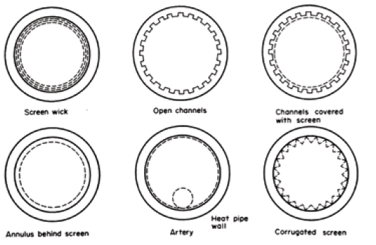
heat wick pipe structure [2]
the hp-1 is a series of high performance, sintered wick structure heat pipes produced by thermacore. these pipes are available in diameters of 6.35 mm (1/4 in), 9.52 mm (3/8 in), 12.7 mm (1/2 in) and 15.89 mm (5/8 in). thermacore corporation tested these 304.8 mm (12 in) long heat pipes with 76.2 mm (in) evaporator and 76.2 mm (3 in) condenser sections at a 100?c operating temperature. the results are presented in figures 4 and 5 [3].
figure 4 shows the temperature difference between evaporator and condenser at different power levels when the heat pipes are vertical. compared to small diameter heat pipes, large diameter heat pipes transport more heat with the same δt. figure 5 illustrates the relationship between power and the inclination angle for different heat pipes. clearly the sintered wick structure pipes are better with the help of gravity. when the inclination angle is larger than 10?, the heat flux that the heat pipes can transport does not vary much. as the inclination angle gradually decreases from 10?c, the heat flux decreases as well. at a -90? angle, the heat flux is less than half of that at 10?.
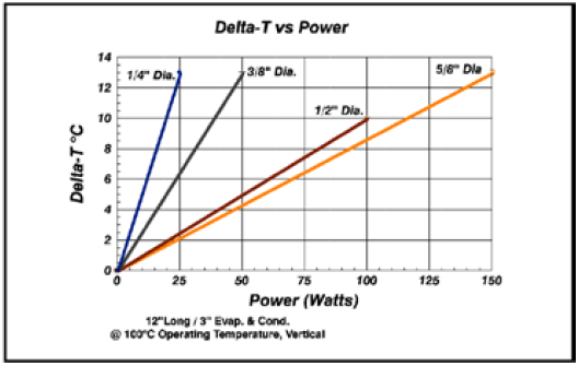
figure 4 hp-1 delt-t vs. power [3]
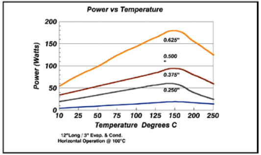
figure 5 hp-1 power vs. angle [3]
loh et al [4] experimentally studied the effects of wick structure and orientation on heat pipe performance. the bench they used for the tests is shown in figure 6. the heat pipes they tested were 4 mm, 5 mm, and 6 mm in diameter. the pipes were 200 mm long with a 35 mm evaporator and a 35 mm condenser. each test started with an inclination angle f of 90°, the vertical position at which the evaporator block was located at the bottom. the tests ran through a 180° rotation that paused at each of the following inclination angles: 60°, 30°, 0° (horizontal), -30°, -60° and –90°.
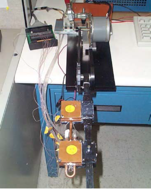
figure 6 photo of heat pipe test bench [4]
figures 7, 8 and 9 show the temperature differences between evaporator and condenser for mesh, groove and sintered metal powder heat pipes, respectively. a heat pipe with a mesh wick structure has the largest thermal impendence. the orientation has a large effect on its heat transfer, but it manages to work at low and moderate heat flux even at a -90° angle. a heat pipe with a groove wick has the smallest thermal impendence among three wick structures when the inclination angle is positive. however, its temperature difference increases dramatically when the inclination angle changes to negative, even at low heat flux. it fails at a negative inclination angle when the heat flux is larger than 15 w. the performance of a heat pipe with sintered metal powder is not affected much by its orientation when the heat flux is less than 15 w. at moderate heat flux, the sintered metal powder heat pipe can still work against gravity with an increased temperature difference. at high heat flux (>25 w), it can only work with help of gravity.
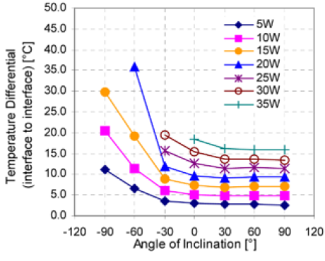
figure 7. δt of a 6mm mesh heat pipe at different inclination angles [4].
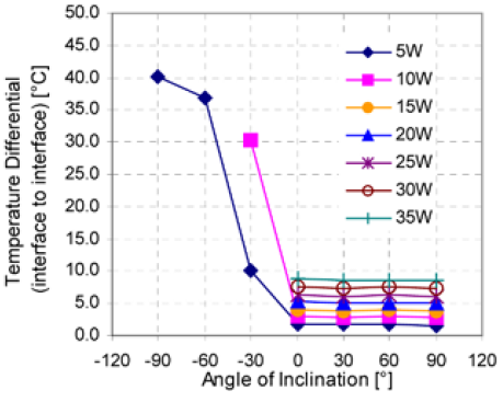
figure 8. δt of a 6mm groove heat pipe at different inclination angles [4].
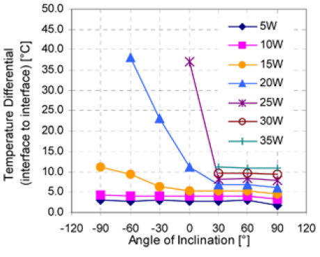
figure 9. δt of a 6mm sintered metal powder heat pipe at different inclination angles [4].
it is important to select the proper wick structure for heat pipes based on their real application. if a heat pipe works in conditions with favorable gravitational force and a few bends, the grooved wick heat pipe is a good choice because of its superior thermal performance. if a heat pipe has complex geometry and works at a small or negative tilting angle, sintered powder metal is the optimum wick structure. for cooling electronic components in telecommunications devices and computer products, the sintered powder metal wick is the best choice because such applications require a compact heat sink size with many turns and bends. the high capillary pumping pressure achieved by using a sintered powder metal wick due to its small pore size, allows a heat pipe to operate in any orientation. other wick structures do not work as well in non-vertical orientations because they cannot lift the returning working fluid along the length of the heat pipe against gravity. references:
references
1. http://www.lightstreamphotonics.com/technology.htm
2. reay, d. and kew, p., heat pipes: theory, design and applications, 5th edition, butterworth-heinemann, 2006.
3. hp-1 heat pipe specification, www.thermacore.com.
4. loh, c., harris, e. and chou, d., comparative study of heat pipes performances in different orientations, semiconductor thermal measurement and management symposium, 2005.
|