|
multi-chip module thermal management
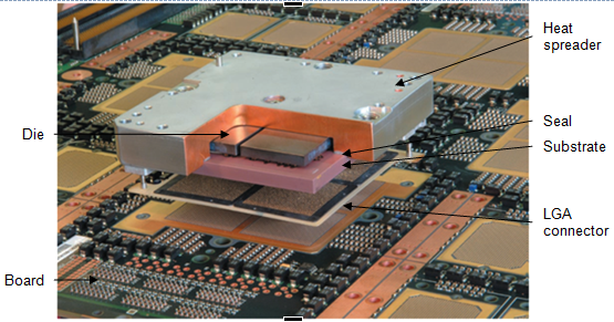
a multi-chip module (mcm) is a specialized electronic package where multiple integrated circuits (ics), semiconductor dies or other discrete components are packaged onto a single substrate, facilitating their use as a single component. a cutaway assembly view of an mcm is shown in figure 1, with various associated components indicated. mcm packaging is frequently used for high-end server systems. in the consumer market, the intel core 2 and i7 processors can be considered mcms, but their power dissipation values are very different from a high-end server. a typical i7 processor has a maximum power dissipation of 130 w or 49.5 w/cm². the recently announced ibm z9 server system mcm uses a total of 16 chips, in which eight chips dissipate 640 w and the total power dissipation is nearly 1 kw [1]. the hitachi mp6000 has 20 chips, with some chips dissipating nearly 600 w for a total maximum power dissipation of 6.5 kw or 100 w/cm² [2].

figure 1. cutaway assembly view of a multichip module (mcm). not shown in this figure is the steel stiffener on the rear side of the board [3].
it is understandable that packaging several high-power chips in an mcm presents considerable thermal and mechanical challenges [1]. these can include:
- achieving and maintaining the thermal gaps due to the close proximity, non-coplanarity and tilts of the multiple chips,
- chip and capacitor re-work,
- sealing the mcm to prevent dry-out of the thermal paste,
- corrosion of the c4s (controlled collapse chip connections), and
- maintaining the package mechanical integrity during the assembly process and operating life.
this article discusses three thermal management techniques used to cool an mcm: a thermal conduction module with direct solder attach cooling (disac), a dual layer thermal interface (tim) thermal design, and an mcm design with small gap technology (sgt) and a hermetic seal.
thermal conduction module with direct solder attach cooling (disac)
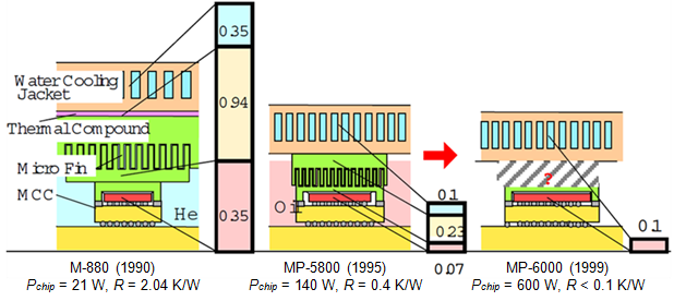
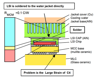
the thermal conduction module is an mcm concept in which the chip is in physical contact with a water-cooled jacket. the evolution of the thermal conduction module can be seen in figure 2. the current design of the hitachi mp6000 is connected to the cooling jacket via solder, the direct solder attach cooling (disac) method. because all the components are connected to solid materials with different thermal expansion coefficients, there is an increase in strain due to the components. in previous generations, the chips were mechanically separated from the heat sink by thermal grease/micro fins in order to reduce the stress on the controlled collapse chip connections (c4). according to [2], the disac design causes nearly all the load induced by module distortion to be supported by the c4. the result of this was that the expected life of the c4 was estimated to be quite short.

figure 2. historical progress from the m-880 to the mp-6000 mcm thermal conduction module concepts. adapted from [2].
with the help of finite element analysis and experiment work, yamada, et al. [2] have been able to clarify the mechanism of c4 strain, improving the module structure to reduce strain and improve the assembly process to reduce defects. some of these changes include:
- reducing the contact area of the solder attachment which makes the temperature on the chip more uniform.
- additional c4 connects were used, although this increases the foot print of the module.
- in addition to the increased number of c4 connections, the outer c4 connections were also reinforced.
- the micro carrier (mcc, see figure 3) was changed from a glass/copper to a tungsten structure. the height of the mcc was also increased.

figure 3. build up sketch of the thermal conduction module with disac [2].
dual layer thermal interface material thermal design
the dual layer thermal interface material thermal design is physically similar to the thermal conduction module, but instead of using solder between the top of the chip and the jacket, the dual layer design uses two different interface materials in combination with a heat spreader material. this is shown in figure 4. the design discussed in this section uses four high-power chips, each with two processors and integrated l2 cache [knickerbocker]. this results in a highly non-uniform power distribution, with regions exceeding 100 w/cm².
to address the high power density, each chip uses an individual heat spreader bonded with adhesive [3]. the thermal resistance of the bond line is minimized by using a very thin layer of thermally conductive adhesive, with an effective conductivity of 1.23 w/m·k. a silicon carbide (sic) heat spreader was selected as it has a coefficient of thermal expansion (cte) similar to that of the chips and a thermal conductivity of 275 w/m·k. having matched ctes avoids thermal stress problems when the module heats up. the heat spreader is optimized by its own thickness as well as the chip spacing. each heat spreader is individually attached so that thin bond lines are maintained. the heat spreader is coupled to the copper hat via an adhesive thermal compound.

figure 4. mcm cross section showing adhesive thermal interface (ati) cooling [3].
the benefit of using the ati, sic heat spreader and atc (advanced thermal compound) in comparison to a solution that only uses an atc, is that the thermal resistance of the atc layer is significantly reduced by having the heat distributed over the spreader. the heat spreaders have more than twice the area of the chips. the combined thermal resistance of the composite structure is less than the atc alone.
mcm with sgt technique with hermetic seal
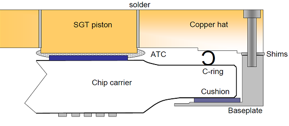
the last of the multi-chip modules discussed in this article uses a thermal paste in combination with small gap technology (sgt) with a hermetic seal as shown in figure 5. the thermal paste is a non-silicone oil based [1]. this minimizes contamination concerns during chip rework.
the small gap technology (sgt) design uses soldered pistons in the copper hat. the pistons are located over the higher power chips. the paste gap between the chip and piston can be individually customized to a required level by reflowing the pistons during the assembly. the high thermal conductivity of the piston and cap allows effective spreading of the heat before it is conducted to a modular refrigeration unit (mru). after the pistons have been reflowed, the parts are removed and the effective atc gap is measured. this is done in order to verify that the hat meets the required specifications. thereafter, the hat is machined before the mru is attached. the mru uses a thin layer of oil as interface material.

figure 5. cross section of the mcm [1].
a multi-chip module requires that chips can be reworked and replaced if found to be electrically defective. therefore, the chips are not underfilled. the well-matched coefficients of expansion of the glass ceramic substrate and the silicon chip allow for the required fatigue life of the c4 connections even when not underfilled. because the c4s are then exposed to the ambient, corrosion concerns arise.
an additional concern is the drying and associated performance loss of the atc when exposed to the ambient [1]. to mitigate both the c4 corrosion and paste drying concerns, a hermetic seal is achieved by a c cross-section ring inserted between the substrate and hat. the c-ring force is supported by a thin polymer cushion which couples the carrier to the steel base plate.
summary
this article has shown that complex design, encapsulation and occasional measurement techniques are required for cooling mcms with significant power dissipation. it has also been discussed that the reliability of an mcm is dependent not only on the effective junction temperature of the individual chips, but also on the mechanical and thermally induced mechanical strain. even with sealing, thermal paste tims remain susceptible to degradation over the life of a product. the mechanism of thermal degradation is the apparent separation of the oil from the filler matrix.
references
- sikka, k., et al., multi-chip package thermal management of ibm z-server systems, itherm 2006.
- yamada, o., sawada, y., harada, m., yokozuka, t., yasukawa, a., moriya, h., saito, n., kasai, k., uda, t., netsu, t., and koyano, k., improvement of the reliability of the c4 for ultra-high thermal conduction module with the direct solder-attached cooling system (disac), ectc 2001.
- knickerbocker, j., leung, g., miller, w., young, s., sands, s., and indyk, r., ibm system/390 air-cooled alumina thermal conduction module, ibm j. res. & dev., vol. 35, no. 3, 1991.
|