|
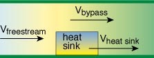
figure 1. wind tunnel configuration.
introduction
while there has been a flurry of activity in literature addressing the behavior of heat sinks in computer electronics, the reusability of the data presented in these papers has been somewhat limited for two reasons:
1) the data presented is application specific.
2) there has never been a standard method for characterizing the behavior of heat sinks.
this paper provides a historical overview of heat sink characterization in commercial electronics, discusses the need for standardization and then provides an overview of recent efforts. only the characterization of cross flow heat sinks will be discussed here. in order to fully define the behavior of such heat sinks, both the flow impedance (pressure drop) and thermal resistance must be characterized. this can be determined either experimentally or analytically. the author hopes that similar efforts will be considered for both natural convection and impingement flow applications in the near future.
historical perspective
with the evolution of the personal computer, the cooling of high power components has moved to the forefront of system design. over the years the power dissipation in the pc s microprocessor has been increasing steadily. for this reason, the use of heat sinks in computers has become more common. this has promoted a flurry of activity in the arena of electronics cooling, with countless papers on characterizing heat sinks.
in almost all of these cases, wind tunnels were used to measure thermal resistance as a function of free stream velocity (see figure 1). with this information, thermal designers could predict the performance of heat sinks in their system and predict the temperature of components using the following equation:
| tcomponent |
= |
tambient+ pcomponent x rheatsink |
where:
| tcomponent |
= |
case temperature of component |
| tambient |
= |
ambient temperature upstream of heat sink |
| pcomponent |
= |
power dissipation of component |
| rheatsink |
= |
thermal resistance of heat sink as a function of velocity |
limitations of the traditional approach
although the previous approach served its purpose at the time, designers realized that there were many limitations to this type of characterization. some of these limitations are as follows:
1) the performance of the heat sink was also a function of the size of the wind tunnel relative to the size of the heat sink.
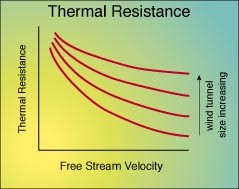
figure 2. thermal resistance.
in figure 2, the thermal resistance of a typical heat sink is shown as a function of free stream velocity and wind tunnel size. the ratio of vbypass/vheat sink changes for a given free stream velocity for different wind tunnel sizes and, thus, the apparent thermal resistance also changes. in addition, knowing the free stream velocity does not give any insight into the channel velocity in the heat sink. so the question arises: what is really being characterized with the wind tunnel test? it is the contention of this author that it is the wind tunnel/heat sink system that is being characterized and not the heat sink. only heat sink applications that match this system exactly can use the thermal resistance data measured with this method.
2) the effect on fan performance was unknown since the airflow resistance of the heat sink was not characterized. the airflow resistance (also known as the flow impedance or pressure drop) of the heat sink is important for understanding how it will perform in a system.
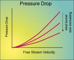
figure 3. pressure drop.
until recently, this aspect of heat sink behavior has been ignored. figure 3 shows the relationship between velocity, pressure drop and wind tunnel size. as with thermal resistance there is no unique curve representing the airflow performance of the heat sink.
3) earlier data was not in a form that can be used in system modeling. for system modeling, heat sinks are represented as volume resistances to limit the size of complex system models as described by patel & belady[1]. in wind tunnel tests, the air flow through the heat sinks is unknown and, therefore, the behavior of the volume in a system flow field cannot be determined. for example, the interaction in multi-heat sink systems cannot be predicted.
4) the tests were not normalized and, thus, comparing the performance between heat sinks was difficult. heat sink a may perform better than heat sink b in a large wind tunnel but the reverse may be true in a smaller wind tunnel. so which is the better heat sink? this depends on the application.
5) finally, wind tunnel measurements have limited resuability. published data by one manufacturer can not be used by another manufacturer unless the applications are identical.
what is needed
the industry desperately needs a standard method for characterizing heat sinks and a method that provides data which can be applied to all applications. if such a method can be developed, the benefits would be as follows:
1) heat sinks can be characterized only once for all applications. the test data would be reusable by the entire industry. this data could be shared by the entire community, who would not have to 'second guess' the test method.
2) test can be quick since parametric studies comparing various wind tunnel sizes would be unnecessary.
3) heat sink manufacturers could provide their customers test data along with their heat sinks without ever needing to understand the application. tests could be done independently and, thus, reduce the number of tests necessary (i.e., one test for all forced convection applications).
4) systems designers can easily incorporate heat sink characteristics into their cfd models, since the volume resistance can be derived from the manufacturers' test data. they would no longer have to model heat sinks just to incorporate the appropriate volume resistance.
in order to reap these benefits, it is critical to understand the flow in the heat sink itself by somehow measuring the mass flow or volumetric flow at standard temperature and pressure (stp). historically, only the flow through the wind tunnel was known, but the airflow through the heat sink and channel velocity was unknown. figure 4 shows a closely ducted wind tunnel.

figure 4. closely ducted confirguration.
for a given approach velocity, the channel velocity in the heat sink is implicitly known. therefore, figures 2 and 3 can be modified as shown in figure 5. note that these curves are shown with the approach velocity as the independent variable. the data could also be presented with volumetric flow or mass flow, since either of these can be derived from the other.
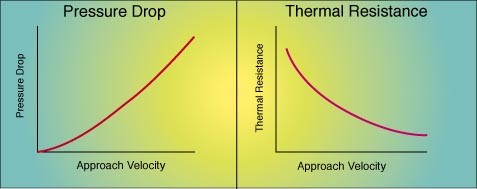
figure 5. pressure drop and thermal resistance to approach velocity.
current efforts
some companies are already using the closely ducted approach for testing heat sinks. hp, for example, has already adopted this type of approach and has seen significant benefits (see reference 1). the hp test uses a flow chamber or metered air source similar to the one in figure 6 that is in accordance with the amca standard 210[2]. figure 7 shows a schematic of the heat sink test fixture. using the flow bench, both the pressure drop and the thermal resistance can be determined simultaneously as a function of volumetric flow. the approach velocity can easily be determined by simply dividing the flow rate by the cross-sectional area of the duct resulting in the data presented in figure 5.
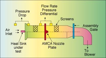
figure 6. flow chamber.
many of hp's divisions now share this test data and, thus, minimize test time while allowing its engineers to focus on system design. the validity under investigation by biber & belady[3]. this published work compares pressure drop measurements with correlations and cfd modeling with excellent agreement. work is under way to validate the thermal resistance as well.
the asme k16 committee has also recognized the need for a useful standard for heat sink characterization and has formed an adhoc subcommittee on heat sink characterization. the charter of this subcommittee is to propose a useful standard that would address the shortcomings of current methods of testing. the subcommittee consists of 11 members from the thermal community from both academia and industry as shown below:
| christian belady (chair) |
hewlett-packard |
| dr. rich wirtz (co-chair) |
university of nevada |
| dr. seri lee |
semi-cool technologies |
| dr. sung jin kim |
korea advanced institute of science & technology |
| dr. cathy biber |
wakefield engineering |
| dr. pradip majumdar |
northern illinois university |
| dr. kaveh azar |
lucent technologies |
| dr. lian-tuu yeh |
lockheed martin vought systems |
| sid west |
texas instruments |
| dr. avram bar-cohen |
university of minnesota |
| dr. alfonso ortega (ex-officio) |
university of arizona |
to date this subcommittee has laid the foundation of the proposal. firstly, and most importantly, the proposal must have buy-in from the heat sink community, both suppliers and customers. secondly, it is imperative that the test procedure be easily reproducible. each aspect of the test setup will be addressed. for example, the committee currently favors the fully ducted test fixture with uniform heating at the base of the heat sink. the target of the committee is to have a preliminary outline of the proposal for the asme national heat transfer conference in baltimore this summer.
summary
as systems become more complex, designers will be forced to focus on system level issues and will devote fewer resources for characterizing heat sinks. therefore, an effective standard allowing simple, reproducible and reusable data will be needed. to achieve this, it is imperative that the characterization tests be independent of the application. to date, the closely ducted approach appears to fill this need. note that this approach is not new. this type of characterization has existed in the defense industry for heat exchangers and cold plates. as the computer industry moves from relatively simple systems (i.e., single processor systems such as pcs) to more sophisticated systems with multiple processors and other critical components, it becomes more apparent that our industry must follow suit.
christian belady
hewlett-packard company
references
| 1. |
patel, c., belady c., "modeling and metrology in high performance heat sink design", porceedings of the 47th electronic components and technology conference, ieee, p.296, san jose, california, 1997. |
| 2. |
ansi/amca standard 210-85. |
| 3. |
biber, c., belady c., "pressure drop predictions for heat sinks: what is the best method?", proceedings of interpack '97 conference, asme, mauna lani, hawaii, 1997. |
|


