|
introduction
there are two main reasons for doing thermal design in the telecommunication industry. the first is to ensure functionality of the equipment and system when subjected to extreme environments. the second is to ensure high dependability of the network. while doing thermal design, many challenges must be kept in mind: the telecommunication system's dependability requirements, expected product lifetime, the product's environmental challenges, component power and power density challenges, as well as the need for fast design cycles in a highly competitive market.
dependability
the largest difference between the telecom industry and the consumer electronics industry is telecom's need for extremely high reliability and dependability. poor reliability in a consumer item leads to poor customer loyalty and lost repeat business, but in telecom it means that and much more. -- when a 911 call is made, equipment reliability can literally be a matter of life and death. traditionally telecom products are extremely dependable -- users have come to expect an immediate dial tone when they lift the receiver, even during a power failure.
equipment reliability is also important to the telephone and datacom service provider companies in the modern, intensely price competitive telecom business. down times of only a few seconds can cause carriers to loose millions of dollars in revenues. also, operating costs for maintenance and replacement are higher unless the equipment is highly dependable throughout its lifetime. this is particularly true for wireless basestations that are often in remote, unmanned locations.
telecom network dependability is a function of many things including architectural redundancy, software robustness and manufacturing process control, but the dependability of the actual electronic hardware on the circuit boards is greatly affected by the temperature of the equipment. this makes proper thermal design a vital part of designing a dependable network. in a poorly designed product, brief excursions to extreme hot or cold can cause "soft failures" where a system drops traffic or stops operating entirely, often due to chip-to-chip timing problems. furthermore, operating electronic components long term at or above the manufacturer's temperature limit will over-stress them, causing non-recoverable "hard failures" that require hardware replacement.
in telecom, there are three main challenges to achieving dependability through good thermal design. they are:
- the widening range of environments which telecom products must withstand. (table 1 lists some of these environments.)
- developing and deploying new products with new technologies during accelerating design cycles with "short design cycle/short product life"
- increasing component power and increasing power density on circuit cards
product environment
modern telecom products are found in all kinds of indoor and outdoor environments. many large telco's still maintain traditional "central offices" with racks of equipment in well controlled, air conditioned rooms with trained maintenance staff. this is the most benign of all the environments, although air conditioner failure still needs to be considered in the design.
slightly more extreme is the "customer premises" environment where private companies or small operators have routers, telephone switches and telephones in occupied work areas or equipment closets. these locations are dirtier; fan noise is often not welcome; and, particularly in closets, temperature and humidity can be higher than in central offices. it is also possible that untrained installation and maintenance staff in these customer premises locations can make thermal problems worse.
the outdoor or "outside plant" equipment sees the most extreme environments. it is possible to deploy an optimum thermal design anywhere in the world without modification. this means a single "world design" will be able to withstand the heat of the arizona desert, the cold of the canadian north, the humidity of thailand, the altitude of columbia and the rapid temperature and humidity changes of st. louis.
sometimes it is not economically sound to include measures for all of these conditions in systems that will only see limited deployment, but the best designs at least have "hooks" in them, allowing these features to be added later with minimal design impact. outside plant equipment must also withstand "attacks" from molds, insects, local fauna and, perhaps, the occasional shot gun blast. figure 1 illustrates the various operating environments.
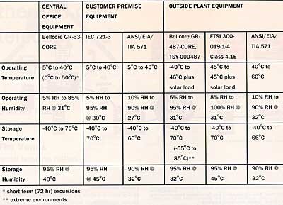
table 1: design environments.
fast design cycles
making a single "world design" leads us into our next challenge: that of developing and deploying new products with new technologies during accelerating design cycles with "short design cycle/short product life". this challenge has become more important as the distinction between telecom products and network products has blurred. a single "world design" avoids the extra time and cost of redesign, retesting and requalification.
this philosophy allows quick sale of an existing product to new and unexpected customers; there is no customizing or requalifying to do. to be effective, however, this "world design" philosophy must be applied to more than just thermal considerations. world safety compliance, electromagnetic compatibility (emc), and telecom compliance, among other things, must also be designed into the product "up front" to achieve fast deployment.
often traditional emc and thermal solutions are at odds with one another. for example, for high frequency processor signals, emc requirements call for some kind of enclosure, limiting cooling air to hot devices. since emc is a regulatory requirement necessary to sell a product and thermal is not, it is most often the thermal solutions that must be innovative (i.e. use of enclosure surfaces as heat sinks or shielding layers in the pcb as heat spreaders), especially in the accelerating design cycle.
this can only be achieved with a parallel design process involving the electrical designer, the emc engineer, the mechanical designer and the thermal engineer. thermal design must therefore be part of the product design process from concept to testing.
also key to providing thermal solutions in the fast design cycle is recognizing future technical challenges and having the solution ready to deploy. although this is an overhead cost, it pays off when a thermal solution is required immediately to get a product out the door. thermal underfill (patent # 5467251) played this role in one of nortel networks' transport products a few years ago allowing for a sealed module emc solution that would have otherwise increased component temperatures to above their operating range.
in the future we will need to have thermal solutions for chip-on-board, integrated passives, and buried passive devices, although at present these technologies are not being widely used in telecom products. these thermal solutions can be developed in-house or co-developed with vendors. keeping up to date with developments presented at conferences and in the literature may also provide solutions.
component power and power density
component powers and power densities are constantly increasing. this is a problem that all electronic packaging designers are facing, not just those engineers in telecom. although the powers and power density values in the telecom industry are not as high as in the super computer industry, it is not uncommon to have to cool 7w to 11w logic devices, 45w power amplifier devices and 60w to 100w on a single pcb. often the pcbs will be in sealed modules making cooling more difficult. this necessitates cooling solutions that will not only cool the hot component but also keep the heat from impacting the surrounding active and passive devices.
the introduction of 3.3v and 2.5v technologies along with higher allowable silicon operating temperatures through better manufacturing process control have recently helped delay the full impact of the power problem. interestingly the limiting factor to board power these days is, in many cases, interconnect related, both in breaking-out and routing the traces on the pcbs and in connector and backplane limitations. as these issues are solved in the next few years, power densities will resume their upward march. this will force a departure from traditional fan cooled frames in air-conditioned rooms, leading to the introduction of liquid cooling.
meeting the challenges:
the nortel networks thermal design process
at nortel networks a four stage thermal design process is used to meet the thermal design challenges:
1. concept
thermal engineering staff must be involved in a multi-disciplinary team at the concept stage of the system packaging design to ensure the right architecture is chosen for the product and its environment. this team includes representatives from thermal, safety, emc, interconnect, manufacturing, human interface, end users and others as required.
the thermal engineer determines, for example, if natural convection is enough to cool the system or if vans are required; what board pitch is sufficient, and so on. hand calculations, technology demonstration vehicles, network models and very simple cfd (computational fluid dynamics) models are all used here. acceptable accuracy of temperature estimates is 25%. power dissipation estimates will often increase as the design involves so margin is required in the cooling strategy.
2. alpha hardware design
detailed thermal analysis is required as more mechanical and electrical details become available. system level cfd tools, pcb level tools and the occasional mock-up build are all used at this stage. acceptable accuracy on the temperature estimates is 10%. note that the accuracy of the analysis is only as good as the input data. this data includes device power dissipation and component thermal properties, both sources of error.
to help reduce these uncertainties, prototype temperature and airflow testing is done as soon as hardware is available. a portable thermal camera, thermocouple datalogger and airflow test equipment are available to allow testing in the development labs where it is possible to exercise the prototype pcbs with test software. since device power estimates can be one of the greatest sources of errors in the thermal analysis, the power estimates can be verified at this stage by comparing infrared images or thermocouple measurements to predicted values. the results of the detailed analysis are used in the design process to aid the mechanical and electrical designers make key decisions and trade-offs.
3. alpha hardware build and test
de-risk and compliance testing is performed in environmental chambers as soon as hardware and software is available. the thermal engineer needs to design the test suite and oversee testing. the thermal engineer should analyze test results to ensure that the cooling design is performing as intended. the thermal engineer should also compare test results to thermal tool predictions as a check on the tool accuracy and analysis approach.
4. validation and compliance test of finalized design
there should be very little thermal engineering left to do at this stage. lab technicians can perform the compliance test suite. the thermal engineer must be aware of detailed test results to gain insight about how the design performs and feedback about how the tools perform.
conclusions
as the telecom and ip industries are converging the design environment is becoming faster and more market-driven. in this intensely competitive environment product dependability, ability to quickly produce designs, and customer service are key differentiating features that will make or break a sale or a company. the thermal designer must meet these challenges and do so as an integral member of the design team.
bonnie mack
nortel networks
ottawa, canada
tim venus, p.e.
nortel networks
ottawa, canada
|


